Table of Contents
Advertisement
Quick Links
TABLE OF CONTENTS
Safety Notices ...................................................................................................... 1
Introduction .......................................................................................................... 3
System Overview ............................................................................................................... 3
Specifications..................................................................................................................... 5
Major Features ..................................................................................................... 7
Performance ...................................................................................................................... 7
Console/Display ................................................................................................................. 7
Compatibility ...................................................................................................................... 7
User Aid ............................................................................................................................. 7
Installation ............................................................................................................ 9
Standard Mounting Bracket ............................................................................................... 9
Installing Console Harnesses .......................................................................................... 10
Installing Implement Harness and Sensors ..................................................................... 11
Key Functions .................................................................................................... 13
On/Off Key ....................................................................................................................... 13
Alarm Cancel Key ............................................................................................................ 13
Enter Key ......................................................................................................................... 13
Escape Key...................................................................................................................... 13
Up and Down Arrow Keys................................................................................................ 13
Left and Right Arrow Keys ............................................................................................... 14
Editing Screen Fields ....................................................................................................... 14
Main Menu Screen ............................................................................................. 15
Monitor Setup .................................................................................................................. 15
Planter Configuration ....................................................................................................... 16
Number of Rows ............................................................................................................................. 16
Row Spacing ................................................................................................................................... 16
Row SetUp (Auto Assigned) ........................................................................................................... 17
Ground Speed Calibration ............................................................................................... 18
Manual Ground Speed Constant Entry ........................................................................................... 19
Help Card......................................................................................................................... 19
Advanced SetUp ................................................................................................ 21
Display & Service............................................................................................................. 21
Service Screen................................................................................................................................ 21
Security ........................................................................................................................................... 22
Limits Setup (Population) (Optional) ................................................................................ 23
Target Population............................................................................................................................ 23
Hi Population/Low Population ......................................................................................................... 24
Population Adjustment .................................................................................................................... 24
Population Response Rate ............................................................................................................. 24
Accessory Setup (Optional) ............................................................................................. 25
Units of Measurement, Backlighting, and Alarm Volume Control ................................................... 26
Auxiliary Modes ................................................................................................. 27
Speed Area Mode ............................................................................................................ 27
Seed Count Mode ............................................................................................................ 27
PM300E and PM332E Planter Monitors
11001-1423-200710
i
Advertisement
Table of Contents

Related Manuals for Dickey-John PM300E


Summary of Contents for Dickey-John PM300E
-
Page 1: Table Of Contents
Population Response Rate ......................24 Accessory Setup (Optional) ..................... 25 Units of Measurement, Backlighting, and Alarm Volume Control ........... 26 Auxiliary Modes ....................27 Speed Area Mode ......................27 Seed Count Mode ......................27 PM300E and PM332E Planter Monitors 11001-1423-200710... - Page 2 Flow Low/Hi Limit Warning ....................38 Failed Ground Speed Sensor ..................39 Battery Hi/Low ......................... 39 Self-Test Failure ......................40 High Ground Speed Exceeded (Optional) ............... 40 Troubleshooting ....................41 Connector Pinouts .................... 45 Warranty......................47 PM300E and PM332E Planter Monitors 11001-1423-200710...
-
Page 3: Safety Notices
Use of the word CAUTION without the safety alert symbol indicates a potentially hazardous situation which, if not avoided, may result in equipment damage. SAFETY NOTICES / 1 PM300E and PM332E Planter Monitors 11001-1423-200710... - Page 4 OPERATOR’S MANUAL 2 / SAFETY NOTICES PM300E and PM332E Planter Monitors 11001-1423-200710...
-
Page 5: Introduction
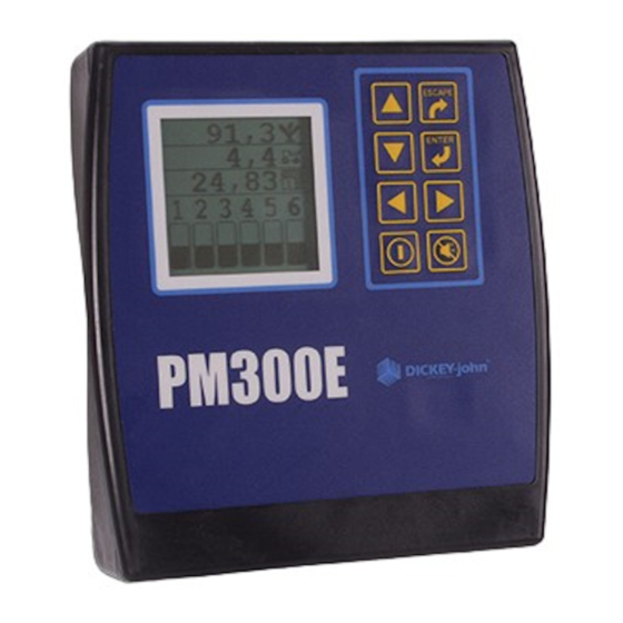
OPERATOR’S MANUAL INTRODUCTION SYSTEM OVERVIEW The DICKEY-john PM300E and PM332E Planter Monitors offer features to monitor 16 and 32 rows respectively. The units monitor seed or fertilizer rows, two hopper levels, and a frequency input (shaft, fan, or flow). The monitors are compatible with DICKEY-john seed, flow, hopper level, and gear sensors. - Page 6 7 8 9 10 11 12 Rows 2, 4, 6, 8 (above limit) alarm Row scan and average spacing with screen blinking symbols and row 1 hi alarm (alarm cancel returns user to operate screen) 4 / INTRODUCTION PM300E and PM332E Planter Monitors 11001-1423-200710...
-
Page 7: Specifications
18.4 cm W x 20.1 cm H x 4.3 cm D (7.3" W x 7.9" H x 1.7" D) Weight 4.4 lbs for 16-row PM300E system 4.8 lbs for 32-row PM332E system *Weight includes console and attached cables (battery power cable and signal cable that extends to the drawbar). - Page 8 OPERATOR’S MANUAL 6 / INTRODUCTION PM300E and PM332E Planter Monitors 11001-1423-200710...
-
Page 9: Major Features
OPERATOR’S MANUAL MAJOR FEATURES PERFORMANCE • Planter monitoring of 16 row (PM300E) or 32 rows (PM332E) • Monitoring of ground speed, two hopper levels, one frequency function (fan, shaft, or flow) • Easy and flexible configuration • Three planting functions viewable during operation: –... - Page 10 OPERATOR’S MANUAL 8 / MAJOR FEATURES PM300E and PM332E Planter Monitors 11001-1423-200710...
-
Page 11: Installation
Save all packing materials until the inspection is complete. If damage is found, immediately file a claim with the carrier and notify your DICKEY-john Sales Representative. STANDARD MOUNTING BRACKET Install the mounting bracket at the desired location using locally acquired... -
Page 12: Installing Console Harnesses
Ground Speed Implement (rows and accessories) *PM300E does not have a second cable PM332E has a 9-pin accessory cable 1. Route the power harness to a +12 V source near the battery if possible. 2. Route the ground speed sensor harness connection to the RADAR, Hall Effect, or GPS ground speed sensor. -
Page 13: Installing Implement Harness And Sensors
The harnesses must not obstruct moving parts of the tractor or implement. Take care when routing harnesses to retain them at proper locations with adequate slack for movement. INSTALLATION / 11 PM300E and PM332E Planter Monitors 11001-1423-200710... - Page 14 OPERATOR’S MANUAL 12 / INSTALLATION PM300E and PM332E Planter Monitors 11001-1423-200710...
-
Page 15: Key Functions
On the Main Operate screen, the arrows are used to navigate between options. On set-up screens, the arrows are used to navigate between options or to change a digit/option. KEY FUNCTIONS / 13 PM300E and PM332E Planter Monitors 11001-1423-200710... -
Page 16: Left And Right Arrow Keys
Editing Screens A highlighted digit can be edited by using the Arrow keys on the Control Panel. Press Enter to accept ESCAPE and confirm the selection. ENTER 122m 00,0 km/h km/h 14 / KEY FUNCTIONS PM300E and PM332E Planter Monitors 11001-1423-200710... -
Page 17: Main Menu Screen
1. Number of rows 2. Row spacing 3. Ground speed constant Row type is an optional entry that can be configured as ON (population), OFF (split row), FLOW (blockage), or DISABLED. MAIN MENU SCREEN / 15 PM300E and PM332E Planter Monitors 11001-1423-200710... -
Page 18: Planter Configuration
OPERATOR’S MANUAL PLANTER CONFIGURATION ENTER The PM300E and PM332E can store three planter configurations for split row planters or multiple planters and seeders. To Select a Planter Configuration (1, 2, or 3): 1. Press the Enter key to display the Main Menu screen. -
Page 19: Row Setup (Auto Assigned)
6. Press the Enter key again to select another row and the Left or Right Arrow key to move to other row units. Press the Escape key to save and return to the Main Operate screen. MAIN MENU SCREEN / 17 PM300E and PM332E Planter Monitors 11001-1423-200710... -
Page 20: Ground Speed Calibration
Selecting the Escape key while the calibration is running will not save the value. 7. Press the Escape key to return to the Main Operate screen. 18 / MAIN MENU SCREEN PM300E and PM332E Planter Monitors 11001-1423-200710... -
Page 21: Manual Ground Speed Constant Entry
Total Area Reset Counter Distance HELP CARD The help card (Figure 11) can be cut out to provide a compact reference for definitions, set-up screens, and general operating information. MAIN MENU SCREEN / 19 PM300E and PM332E Planter Monitors 11001-1423-200710... - Page 22 No flow Hopper Low All Rows Failed Planter Lifted No Speed Input Stop Configuration Start Reset Security Password Save Password English/Metric Back light Graphic/Text Label Alarm Population Adjust Response Rate 20 / MAIN MENU SCREEN PM300E and PM332E Planter Monitors 11001-1423-200710...
-
Page 23: Advanced Setup
0 2 0 5 0 3 0 7 1 4 software versions Total hours of operation 15,20 Total hectares covered 13,1 Battery voltage Hopper Level 1 and 2 Lift switch sensor status status ADVANCED SETUP / 21 PM300E and PM332E Planter Monitors 11001-1423-200710... -
Page 24: Security
Password Screen and Lock/Unlock Screen Enter Default 0000 Password Create a New III.I 0000 Password III.I 1 2 3 1,2,3 . . . Highlight Configuration icon to access the Lock/Unlock screen 22 / ADVANCED SETUP PM300E and PM332E Planter Monitors 11001-1423-200710... -
Page 25: Limits Setup (Population) (Optional)
5. When the field shows the desired target population, press the Enter key to confirm the selection. 6. Press the Escape key to return to the Main Operate screen. ADVANCED SETUP / 23 PM300E and PM332E Planter Monitors 11001-1423-200710... -
Page 26: Hi Population/Low Population
1. Move the slide to the right when planting high seed rates and to the left when planting low seed rates, refer to (Figure 15). 2. Press the Escape key to return to the Main Operate screen. 24 / ADVANCED SETUP PM300E and PM332E Planter Monitors 11001-1423-200710... -
Page 27: Accessory Setup (Optional)
5. Stop the monitor calibration by selecting the Enter key again. Stop symbol 6. Highlight the revolutions or liquid level window. 7. Select the Enter key. 8. Enter the number of revolutions (shaft/fan) or liters (flow). ADVANCED SETUP / 25 PM300E and PM332E Planter Monitors 11001-1423-200710... -
Page 28: Units Of Measurement, Backlighting, And Alarm Volume Control
3. Press Enter to highlight the setting to change and the Up and Down Units Arrow key to cycle through selection. 4. Press Enter to confirm the desired selection. Backlight Alarm Volume 26 / ADVANCED SETUP PM300E and PM332E Planter Monitors 11001-1423-200710... -
Page 29: Auxiliary Modes
Refer to the Advanced Setup Reset option section for additional 9,521 9,521 information. 9,521 9,521 9,521 9,521 9,521 9,521 9,521 9,521 1,2,3... 9,521 9,521 9,521 9,521 Seed Count Mode icon 9,521 9,521 9,521 9,521 AUXILIARY MODES / 27 PM300E and PM332E Planter Monitors 11001-1423-200710... - Page 30 OPERATOR’S MANUAL 28 / AUXILIARY MODES PM300E and PM332E Planter Monitors 11001-1423-200710...
-
Page 31: Operate Mode
Password screen. 1 = Average population Refer to the Advanced Setup 2 = Speed section for additional information. 3 = Field area 4 = Total area 5 = Shaft RPM OPERATE MODE / 29 PM300E and PM332E Planter Monitors 11001-1423-200710... -
Page 32: Changing Graphic Or Text Icons
To Change the Graphic/Text Settings: display the Password screen. 1. At the Main Menu screen, highlight the Display & Service icon and Refer to the Advanced Setup press Enter. section for additional information. 30 / OPERATE MODE PM300E and PM332E Planter Monitors 11001-1423-200710... -
Page 33: Changing Planting Parameters
Average Spacing displays the average seed spacing (cm or inches) of the planter's rows that are configured for population. This function can be labeled with a symbol or text, depending on the text/graphic setting. OPERATE MODE / 31 PM300E and PM332E Planter Monitors 11001-1423-200710... -
Page 34: Minimum/Average/Maximum Spacing
Total Area (ha3/ac3) displays the total field area in hectares (ha) or acres (ac) depending on the Metric/English setting. This function can be labeled with a symbol or text, depending on the text/graphic setting. 32 / OPERATE MODE PM300E and PM332E Planter Monitors 11001-1423-200710... -
Page 35: Speed
Shaft function displays the shaft's speed in revolutions per minute (RPM). FLOW Flow displays the flow rate speed in liters per hectare (l/ha) or gallons per acre (g/ac) depending on the Metric/English setting. OPERATE MODE / 33 PM300E and PM332E Planter Monitors 11001-1423-200710... -
Page 36: Customizing The Lower Parameter Window
1 2 3 4 5 6 7 8 9 1 2 3 4 5 6 10 11 12 13 14 15 16 17 18 Large Row Indicators Small Row Indicators Medium Row Indicators 34 / OPERATE MODE PM300E and PM332E Planter Monitors 11001-1423-200710... -
Page 37: Alarms
2. Power on/off sequence occurs before problem is corrected. 3. An All Rows Failure alarm occurs then the console again detects less than 2 seeds per second through the seed tube. ALARMS / 35 PM300E and PM332E Planter Monitors 11001-1423-200710... -
Page 38: All Rows Failure
Typical scenarios to activate an All Row Failure alarm: 1. Tractor is stopped while planter is in the ground. 2. Tractor is operating with planter lifted. 3. Normal “end of run” turn around. Figure 26 All Rows Failure Display 36 / ALARMS PM300E and PM332E Planter Monitors 11001-1423-200710... -
Page 39: Hi/Low Population Warning
Setup mode. Alarm can be silenced by pressing Alarm Cancel key, but will re-activate if problem is not resolved. Figure 28 Fan Speed Limit Warning Display (Optional) LOW FAN SPEED HIGH FAN SPEED ALARMS / 37 PM300E and PM332E Planter Monitors 11001-1423-200710... -
Page 40: Shaft Speed Low/Hi Limit Warning
Flow Lo or Hi Limits in the Setup mode. Alarm can be silenced by pressing Alarm Cancel key, but will re-activate if problem is not resolved. Figure 30 Flow Low/ Hi Limit Warning Display (Optional) HIGH FLOW RATE LOW FLOW RATE 38 / ALARMS PM300E and PM332E Planter Monitors 11001-1423-200710... -
Page 41: Failed Ground Speed Sensor
The alarm cannot be shut off and will continue to sound until corrective action is taken. Figure 32 Battery Failure Display HI BATTERY VOLTAGE 1 6 ,5 Seeds Per Distance Row Scan ALARMS / 39 PM300E and PM332E Planter Monitors 11001-1423-200710... -
Page 42: Self-Test Failure
Ground Speed Setup screen. Alarm can be silenced by pressing the Alarm Cancel key. Figure 34 Maximum Speed Exceeded Warning Display (optional) HI GROUND SPEED 40 / ALARMS PM300E and PM332E Planter Monitors 11001-1423-200710... -
Page 43: Troubleshooting
OPERATOR’S MANUAL TROUBLESHOOTING TROUBLESHOOTING / 41 PM300E and PM332E Planter Monitors 11001-1423-200710... - Page 44 2. Be sure connections are clean and tight. Inspect harness for damage. 3. Check all harnesses for pinches or breaks that can cause power or 8V sensor power short to ground. 42 / TROUBLESHOOTING PM300E and PM332E Planter Monitors 11001-1423-200710...
- Page 45 LED, swap harness connection with adjacent sensor to determine if sensor or harness is damaged. Replace sensor or harness. 2. Console is damaged. Contact dealer or DICKEY-john Europe (+33-141-192-180). TROUBLESHOOTING / 43 PM300E and PM332E Planter Monitors 11001-1423-200710...
- Page 46 OPERATOR’S MANUAL 44 / TROUBLESHOOTING PM300E and PM332E Planter Monitors 11001-1423-200710...
-
Page 47: Connector Pinouts
PM332E 9-pin Cable Assembly Pin # Description Pin # Description Ground (black) Lift Switch Signal (green) Hopper #1 Power (red) Hopper #2 Sense (white) Shaft +12V Switched Sensor Return RS232 Rx RS232 Tx CONNECTOR PINOUTS / 45 PM300E and PM332E Planter Monitors 11001-1423-200710... - Page 48 OPERATOR’S MANUAL 46 / CONNECTOR PINOUTS PM300E and PM332E Planter Monitors 11001-1423-200710...
-
Page 49: Warranty
Europe: DICKEY-john Europe S.A.S, 165, boulevard de Valmy, 92700 – Columbes – France TEL: 33 (0) 1 41 19 21 80, FAX: 33 (0) 1 47 86 00 07 WEB: www.dickey-john.eu Copyright 2007 DICKEY-john Corporation Specifications subject to change without notice.
Need help?
Do you have a question about the PM300E and is the answer not in the manual?
Questions and answers