
Related Manuals for Fisher-Rosemount Chempure Series

Summary of Contents for Fisher-Rosemount Chempure Series
- Page 1 Instruction Manual P/N 51-Chemp Chempure™ Series May 1997 Continuous Flow Analyzers Chempure...
- Page 2 WARNINGS ESSENTIAL INSTRUCTIONS ELECTRICAL SHOCK HAZARD!! READ THIS PAGE BEFORE PROCEEDING! • Installation of cable connections and servicing of Your purchase from Rosemount Analytical, Inc. has result- this product require access to shock hazard volt- ed in one of the finest instruments available for your par- age levels.
- Page 3 CHEMPURE MANUAL TABLE OF CONTENTS Chempure ™ TABLE OF CONTENTS SECTION TITLE .......................... PAGE Introduction....................... Unpacking ......................... Instrument Description.................... Analyzer Front View....................3.1.1 Main Cabinet ......................3.1.2 Reagent Cabinet ......................Keypad Panel ......................3.2.1 Panel ........................... 3.2.1 Keypad ........................Electronics Panel ......................3.3.1 Electronic Panel......................
- Page 4 CHEMPURE MANUAL TABLE OF CONTENTS TABLE OF CONTENTS (CON’T) SECTION TITLE .......................... PAGE Calibration and Operation ..................Auto Calibration ......................Manual Baseline Correction..................Manual Fullscale Calibration..................Sample Analysis ......................Shutdown ........................Overnight Shutdown....................Shutdown for a Few Days or More................After Overnight Shutdown..................
- Page 5 CHEMPURE MANUAL TABLE OF CONTENTS TABLE OF CONTENTS (CON’T) SECTION TITLE .......................... PAGE Preventive Maintenance ..................10.1 Maintenance Schedule ....................10.1.1 Weekly ........................10.1.2 Monthly ........................10.1.3 Quarterly ........................10.1.4 Yearly .......................... 10.2 Maintenance Procedures................... 10.2.1 NaOH Fluidics Wash (Silica Only) ................10.2.2 Pump Tubing Harness Replacement.................
-
Page 6: Table Of Contents
CHEMPURE MANUAL TABLE OF CONTENTS TABLE OF CONTENTS (CON’T) LIST OF FIGURES FIGURE TITLE .......................... PAGE Analyzer Front View....................Keypad Panel ......................Electronics Panel ......................CPU Board........................Fault/Analog Board..................... Colorimeter Assembly ....................Pump Assembly Components ................... Back of Analyzer ......................Input/Output Panel ..................... - Page 7 – This instruction manual describes installation, opera- unattended – for a month or more. Maintenance is tion, and maintenance of the Chempure Series ana- simplified by a modular design with quick disconnect lyzers. The specific chemistry of your individual ana- fittings and color coded components.
-
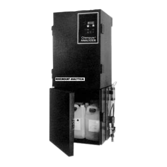
Page 8: Analyzer Front View
CHEMPURE MANUAL SECTION 3 INSTRUMENT DESCRIPTION SECTION 3 INSTRUMENT DESCRIPTION 3.1 ANALYZER FRONT VIEW Part Function Pump Assembly Positive displacement, peristaltic 3.1.1 MAIN CABINET pump moves sample and Part Function reagents through analyzer. Main Cabinet Splash-proof enclosure protects Reaction Vessel Contains chemistry module, analyzer. - Page 9 CHEMPURE MANUAL SECTION 3 INSTRUMENT DESCRIPTION (2X) FIGURE 3-1 ANALYZER FRONT VIEW...
-
Page 10: Keypad Panel
CHEMPURE MANUAL SECTION 3 INSTRUMENT DESCRIPTION FIGURE 3-2 KEYPAD PANEL 3.2 KEYPAD PANEL Button/LED Function auto multi-stream Press to begin automatic Multi- 3.2.1 PANEL Stream analysis (Multi-Stream Part Function analyzer only). Thumbscrews Attaches keypad to analyzer and man. baseline Press to begin manual baseline secures door to electronics panel. -
Page 11: Electronics Panel
CHEMPURE MANUAL SECTION 3 INSTRUMENT DESCRIPTION FIGURE 3-3 ELECTRONICS PANEL 3.3 ELECTRONICS PANEL Part Function Multi-Stream and Circuit board controls Stream The electronics panel is located directly behind the key- Multi-RS-232C accessory and Interface Board pad. Access electronics panel by removing thumb- RS-232C interface. -
Page 12: Cpu Board
CHEMPURE MANUAL SECTION 3 INSTRUMENT DESCRIPTION FIGURE 3-5 FAULT/ANALOG BOARD FIGURE 3-4 CPU BOARD 3.3.3 FAULT/ANALOG BOARD 3.3.2 CPU BOARD Part Function Part Function Leak Detector Adjusts sensitivity of leak 20 mA Adjust For adjustment of fullscale Adjust Set Screw detector. -
Page 13: Colorimeter Assembly
CHEMPURE MANUAL SECTION 3 INSTRUMENT DESCRIPTION (SEE FIGURE 12-1) FIGURE 3-6 COLORIMETER ASSEMBLY 3.4 COLORIMETER Part Function Colorimeter Contains and protects Housing colorimeter and electronics which measure the absorbance of the reacted sample solution. Source Lamp Provides light source for col- orimeter. -
Page 14: Pump Assembly Components
CHEMPURE MANUAL SECTION 3 INSTRUMENT DESCRIPTION FIGURE 3-7 PUMP ASSEMBLY COMPONENTS 3.5 PUMP AND REACTION VESSEL Part Function ASSEMBLY Quick-Disconnect Male half of tubing Connector connector which mates with Part Function pump tubing harness. Pump Housing Contains and protects pump Colorimeter Inlet Tubing carries sample, after and reaction vessel assembly. -
Page 15: Back Of Analyzer
CHEMPURE MANUAL SECTION 3 INSTRUMENT DESCRIPTION 3.6 BACK OF MAIN CABINET In the back of the main cabinet are a number of elec- tronic components and connectors. INPUT/OUTPUT PANEL SOLENOID VALVE #3 CON- NECTOR FIGURE 3-8 BACK OF ANALYZER WITH COVER REMOVED... -
Page 16: Input/Output Panel
CHEMPURE MANUAL SECTION 3 INSTRUMENT DESCRIPTION 3.7 INPUT/OUTPUT PANEL The input/output panel is located on the upper, left side of the analyzer. FIGURE 3-9 INPUT/OUTPUT PANEL 3.8 COMPUTER INTERFACE The computer interface ports are located on the lower, left side of the analyzer. Part Function Printer Interface... -
Page 17: Overflow Sampler Assembly
CHEMPURE MANUAL SECTION 3 INSTRUMENT DESCRIPTION 3.9 OVERFLOW SAMPLER ASSEMBLY Part Function The overflow sample assembly is located is on the Sample Inlet Tube Tubing which carries sample from overflow tube to sample lower right side of the Analyzer (See Figure 3-1) solenoid valve #1. -
Page 18: Mounting Main And Reagent Cabinets
CHEMPURE MANUAL SECTION 4 INSTALLATION SECTION 4 INSTALLATION After the analyzer has been unpacked and all parts accounted for, install as described in the following chapter. 4.1 MAIN CABINET MOUNTING 4.1.1 GENERAL RECOMMENDATIONS: • Mount the cabinet on a wall or other suitable verti- cal surface, at least 66"... -
Page 19: Overflow Sampler Assembly
CHEMPURE MANUAL SECTION 4 INSTALLATION 4. Supply sample stream to regulating/intake valve with 1/4" tubing (plastic or steel) as follows: 4.4 OVERFLOW SAMPLER ASSEMBLY a. Loosen and remove nut and compression fitting To mount overflow sampler assembly, proceed from bottom of regulating intake valve. as follows: b. -
Page 20: Pump Platen Removal
CHEMPURE MANUAL SECTION 4 INSTALLATION FIGURE 4-3 PUMP AND REACTION VESSEL ASSEMBLY FIGURE 4-4 PUMP PLATEN REMOVAL... -
Page 21: Pump And Reaction Vessel Assembly
CHEMPURE MANUAL SECTION 4 INSTALLATION Terminals are provided for ground, power supply, hi/lo NOTE alarms, output signals, and status signals. Use Romex connectors to hold cables securely in holes above input/output panel. Output signals – a voltage output of 0-5 VDC and a float- ing, ungrounded current output of 4 - 20 mA are avail- 4.6 COLORIMETER able for remote readout or control of a process. -
Page 22: Installation Of Pump Tubing Harness
CHEMPURE MANUAL SECTION 4 INSTALLATION 6. Remove platen assembly from pump by lifting plat- 3. Stretching with right hand, place right hand set of en cover 90 degrees and then lifting off. See tubing shoulders into right end blocks. Make sure Figure 4-4. - Page 23 CHEMPURE MANUAL TABLE OF CONTENTS 4.9 FLUIDICS tion, into waste tube. 4.10 REAGENTS Set up system fluidics as follows: 1. Place colorimeter inlet tubing into the flow cell inlet 1. Remove screw caps from reagent bottles. (see Figures 4-3 and 3-6). 2.
-
Page 24: Basic Functional Diagram
5.4 SPECIFIC ANALYZER CHEMISTRY The Chempure Series analyzers accommodate a great 5.2 KEYPAD LOCK number of chemistries. The basic analyzer operation For normal operation, the only buttons needed are auto remains the same but flow cell, interference filter, cal, tube reset, and enter. - Page 25 CHEMPURE MANUAL SECTION 6 START-UP SECTION 6 START-UP 4. Pull pump forward and check leak detector by dip- 6.1 OVERFLOW SAMPLER ASSEMBLY ping finger in tap water and touching leak detector 1. Ensure that temperature of sample stream is behind pump. Leak detector LED on status panel between 0 and 50°C (30 and 122°F).
- Page 26 CHEMPURE MANUAL SECTION 7 CALIBRATION AND OPERATION SECTION 7 CALIBRATION AND OPERATION The Chempure analyzer has the flexibility to be calibrat- 6. After a few more minutes sample stream will begin ed either manually or automatically.Generally, automatic to wash through the system. Sample measurement calibration is the best method to use, because it not only is beginning and concentration values will be dis- performs the calibration but automatically recalibrates...
- Page 27 CHEMPURE MANUAL SECTION 8 SHUTDOWN SECTION 8 SHUTDOWN 8.1 OVERNIGHT SHUTDOWN 8.4 AFTER SHUTDOWN OF A FEW DAYS OR MORE 1. Remove reagent straws from reagent containers and place in container of deionized water. 1. Replace reagent straws into appropriate reagents. 2.
- Page 28 SECTION 9 ACCESSORIES To make analysis easier and faster, the following option- 9.1.1 SPAN ADJUSTMENT al accessories may be used with the Chempure Series For recorders with span adjustment: analyzer: 1. Press rec. zero to output zero volts on • Chart Recorders 0-5V output and 4mA on 4-20mA output.
-
Page 29: Trace Recording
CHEMPURE MANUAL SECTION 9 ACCESSORIES The analyzer will operate as normal, with data output to the chart recorder. In addition to the sample reading, there will be a recorder trace for each baseline and fullscale calibration. In normal operation a baseline cali- bration is performed once every 12 hours and a base- line and fullscale calibration performed once every 48 hours. -
Page 30: Multi-Stream Circuit Board
CHEMPURE MANUAL SECTION 9 ACCESSORIES 9.3 MULTI-STREAM ANALYSIS 4. Hold circuit board with card connector away from you and components on the right side of board (do A microprocessor based valve switching system can be not touch!) installed to allow analysis of multiple sample streams. 5. - Page 31 CHEMPURE MANUAL SECTION 9 ACCESSORIES 2. Remove 4 bolts holding panel onto outside of 7. If installing RS-232C and Printer option, connect reagent cabinet, set aside single stream overflow large ribbon connector to multi-stream board. sampler assembly. 8. If installing Relay Output option, connect small rib- bon connector to multi-stream board.
- Page 32 CHEMPURE MANUAL SECTION 9 ACCESSORIES Display Action 4. When finished analyzing that stream: a. Press man. multi-stream to select another 5. 3015 Display indicates stream #3 for a time stream; or, of 15 minutes. b. Press auto multi-stream to begin automatic Change by scrolling or just press analysis cycle.
- Page 33 CHEMPURE MANUAL SECTION 9 ACCESSORIES 9.5.2 DATA CONFIGURATION 9.5.4 RS232-C START-UP The computer must be set to match the fixed data 1. With the computer and the CFA-1000 turned off, configuration of the analyzer, which is: connect the RS232-C cable to the computer and to the RS232-C port on the CFA-1000.
- Page 34 CHEMPURE MANUAL TABLE OF CONTENTS SETDECI below.) 9.6 PRINTER INTERFACE Command Function The printer interface is a female parallel port designed to be compatible with IBM PC type cables and printers. SETFSNO To change fullscale value. For exam- This built-in capability permits text printing only, no ple, to change fullscale to 200, enter graphics.
- Page 35 CHEMPURE MANUAL SECTION 9 ACCESSORIES 9.7.3 MULTI-STREAM OPERATION c. Month, two digits Jan = 01, Feb = 02, etc. The printer will print the last value of a stream automati- Press Enter. cally just as the system switches to the next stream. To print at timed intervals as well, follow the procedure out- d.
- Page 36 CHEMPURE MANUAL SECTION 10 PREVENTIVE MAINTENANCE SECTION 10 PREVENTIVE MAINTENANCE Your Chempure Series analyzer is a precision instru- 10.2 MAINTENANCE PROCEDURES ment which, if maintained properly, should provide 10.2.1 NAOH FLUIDICS WASH years of accurate and reliable service. (SILICA ANALYZER ONLY) A monthly wash with a dilute sodium hydroxide solution 10.1 MAINTENANCE SCHEDULE...
- Page 37 CHEMPURE MANUAL SECTION 10 PREVENTIVE MAINTENANCE 5. Place quick disconnect connector into holding 10.2.4 INTERFERENCE FILTER CLEANING clamp on front of the pump housing. 1. Loosen thumbscrew on top of interference filter 6. Replace platen. assembly (see Figure 3-6). 7. Turn pump power ON. 2.
- Page 38 CHEMPURE MANUAL SECTION 11 TROUBLESHOOTING SECTION 11 TROUBLESHOOTING The troubleshooting chapter is divided into two sec- 11.1 TROUBLESHOOTING CHART tions: Symptoms observed during operation are generally • Troubleshooting Chart – A list of symptoms, proba- enough to identify a faulty component. Such symptoms, ble causes, and remedies.
- Page 39 CHEMPURE MANUAL SECTION 11 TROUBLESHOOTING Problem Probable Cause Remedy Silica analyzer flow Reagent deposits Rinse fluidics with 0.5N NaOH, see 10 cell is blue Preventive Maintenance Chemical residue or Chemical spill Clean pump rollers with damp cloth; if needed, black lines on pump use lacquer thinner rollers Pump rollers do not...
-
Page 40: Source Lamp Replacement
SECTION 12 REPAIR AND SERVICE SECTION 12 REPAIR AND SERVICE The Chempure Series analyzers are designed with 12.1.1 SOURCE LAMP REPLACEMENT modular components for quick and easy repair. 1. Let old source lamp cool down. Following are repair and replacement instructions for 2. - Page 41 CHEMPURE MANUAL SECTION 12 REPAIR AND SERVICE FIGURE 12-2 INTERFERENCE FILTER AND SAMPLE FLOW CELL REPLACEMENT Install new pump tubing harness as follows: 12.2 PUMP AND REACTION VESSEL ASSEMBLY 1. Hold quick disconnect end of tubing harness in left hand and free end of tubing in right hand (white tab 12.2.1 PUMP TUBING HARNESS REPLACEMENT on collars should be on top).
-
Page 42: Pump Platen Removal
CHEMPURE MANUAL SECTION 12 REPAIR AND SERVICE FIGURE 12-3 PUMP PLATEN REMOVAL FIGURE 12-4 INSTALLATION OF PUMP TUBING HARNESS... -
Page 43: Circuit Boards
CHEMPURE MANUAL SECTION 12 REPAIR AND SERVICE assembly. 12.2.2 REACTION VESSEL ASSEMBLY REPLACEMENT 13. Turn power ON. 1. While system is still running, disconnect sample 14. Perform automatic calibration. tubing from left side of solenoid valve #1, at the 12.3 CIRCUIT BOARDS nipple connection. -
Page 44: Wiring Diagram
CHEMPURE MANUAL SECTION 13 APPENDIX SECTION 13 FIGURE 13-1 WIRING DIAGRAM... - Page 45 CHEMPURE MANUAL SECTION 13 APPENDIX CHEMPURE SERIES “HELP SHEET” (SINGLE STREAM) • leak • calibration • lamp • pump tube enter • • • auto fullscale baseline • • alarm alarm • tube power reset zero PRESS OPERATIONS TO EXIT PRESS...
- Page 46 CHEMPURE MANUAL SECTION 13 APPENDIX...
- Page 47 CHEMPURE MANUAL SECTION 16 APPENDIX SPECIFIC CHEMISTRIES Method: SODIUM-01A (0-10, 0-100 ug/l (ppb)) Method: Silica-01A (0-100 ppb ug/l) SODIUM IN WATER RANGE: 0-10, 0-100 ug/l (ppb) SILICA IN BOILER WATER & FEEDWATER RANGE: 0-100ppb (ug/l) GENERAL DESCRIPTION GENERAL DESCRIPTION Sodium ion is measured potentiometrically using ion selective electrodes.
- Page 48 CHEMPURE MANUAL SECTION 13 APPENDIX Method: Hydrazine -02A (0-200 ppb) Method: Phosphate-02A (0-3 mg/l, 0-5 mg/l, 0-10 mg/l) HYDRAZINE IN BOILER WATER RANGE: 0-200 ppb (ug/l) PHOSPHATE IN BOILER WATER (RANGE: 0-3 mg/l, 0-5 mg/l, 0-10 mg/l P) GENERAL DESCRIPTION GENERAL DESCRIPTION The automated procedure for the determination of hydrazine is based on the reaction with pdimethy-...
- Page 49 CHEMPURE MANUAL SECTION 14 ORDERING INFORMATION SECTION 14 ORDERING INFORMATION 14.1 REAGENTS Description Part Number Solenoid Valve, 180-B301-01 Reagents for CFA-1000 Series analyzers are available Multi-Stream Valve Panel from Scientific Instruments on a contract basis. Tygon Tubing, 562-O009-01 Refer to your method sheet in CHEMISTRY SECTION 3/16"...
- Page 50 CHEMPURE MANUAL SECTION 15 SPECIFICATIONS SECTION 15 SPECIFICATIONS Dimensions 18" wide x 28" high x 15" deep (without reagent cabinet) Weight 126 pounds (57 Kg) With reagents ~176 pounds (80Kg) Electrical Requirements 115V ± 10%, 60 Hz (230V ± 10% Available as option) Sample Requirements 10-15 mL/minute, pressure less than 10 psig, tempera- ture 32°-122°F, filtered to 10 microns.
- Page 51 WARRANTY Goods and part(s) (excluding consumables) manufactured by Seller are warranted to be free from defects in work- manship and material under normal use and service for a period of twelve (12) months from the date of shipment by Seller. Consumables, pH electrodes, membranes, liquid junctions, electrolyte, O-rings, etc. are warranted to be free from defects in workmanship and material under normal use and service for a period of ninety (90) days from date of ship- ment by Seller.
- Page 52 The right people, the right answers, right now. UNILOC DIVISION CUSTOMER SUPPORT CENTER 1-800-854-8257 ON-LINE ORDERING NOW AVAILABLE ON OUR WEB SITE http://www.RAuniloc.com Credit Cards for U.S. Purchases Only. Rosemount Analytical Inc. Uniloc Division 2400 Barranca Parkway Irvine, CA 92606 USA Tel: (949) 863-1181 http://www.RAuniloc.com ©...
Need help?
Do you have a question about the Chempure Series and is the answer not in the manual?
Questions and answers