
Summary of Contents for ETH-messtechnik DRBK
- Page 1 +49 (0) 79 72 93 10-0 hagstrasse 10 . D-74417 gschwend messtechnik sales@eth-messtechnik.de Operating Instructions Torque Sensor DRBK / DRBK-n DRBK-A English...
- Page 2 messtechnik © ETH messtechnik gmbh This operator manual is not a quality agree- ment or durability guarantee as set out in Section 443 of the German Civil Code. Specification changes, typing and printing errors reserved.
-
Page 3: Table Of Contents
11. Disposal ........................16 13. Datasheet ........................ 17 13.1 Technical specifications ..................18 13.2 Mechanical dimensions DRBK ................19 13.3 Sizes DRBK ......................19 13.4 Mechanical dimensions DRBK-A ..............20 13.5 Sizes DRBK-A ....................20 13.6 Mechanical values and load limits DRBK + DRBK-A ........21... -
Page 4: Important Instructions
Important instructions: The torque transducers of the DRBK-A series can be used as machine elements (e.g. test bench). In the case of mass-critical applications, the installation positi- on of the drive and measurement side must be taken into account. -
Page 5: Introduction
messtechnik 1. Introduction Torque transducers measure torques in Nm. 2. Field of application and application instructions The torque transducers measure both right-hand and left-hand loads. With a right-hand load, the signal direction is positive. The nameplate provides informa- tion about the final value of the measuring range. The torque transducers measure dynamic moments just as precisely as static torques. -
Page 6: Structure And Mode Of Operation
The strain gauges are arranged in a Wheatstone bridge circuit. The non-positive connection takes place via suitable couplings on the cylindrical shaft ends. Optionally, the torsion shaft of the DRBK can be equipped with a speed measure- ment (see data sheet). 3.2 Case The torque transducer housings are made of high-strength aluminum and the surface is hard-anodized for protection. -
Page 7: Disturbances And Their Compensation
messtechnik 3.4 Disturbances and their compensation Avoid bending, axial and radial forces. When you have problems with this, use ETH clutches. To connect the transducer to a measurement unit you need a shielded cable. The transducers are EMC-tested and are complying with EN 55011:1998 + A1:1999 + A2:2002 EN 61326-1:2006-05 and EN 61000-6-2:2005. -
Page 8: Conditions On Location
messtechnik 4. Conditions on location 4.1 Ambient temperature For best results, the device must be operated within the nominal temperature range. The best operating conditions are constant and, if necessary, slowly changing temperatures. The specified temperature errors apply if the tempera- ture does not change faster than 5K/h. -
Page 9: Mechanical Installation
messtechnik 5. Mechanical installation 5.1 Precautions when assembling • Handle transducer carefully. • Important note: When installing the couplings, do not overload the transducer, not even temporarily. It is strongly recommended to remove the transducer before mounting connect electrically and the torque signal with too monitor in order not to exceed the measuring range! •... -
Page 10: Structure Of The Measurement Chain
messtechnik 6. Structure of the measurement chain In order to be able to measure with the transducer, a complete measurement chain must be set up. This consists of: • torque transducer • connection cable We recommend using our ETH cables. They are optimized in design and shielding. -
Page 11: Connection
messtechnik 7. Connection Connection of a torque transducer with a 12-pin connector... -
Page 12: Hints For Connection
messtechnik 7.1 Hints for connection Electric and magnetic fields cause interference with the measuring signal. This interference is mainly caused by power cords, relays or motors installed nearby. Besides these, interference can be caused by multiple grounding of the measure- ment chain on more than one point. -
Page 13: Pinout
8. Pinout • Standard measuring cable AK12.4 • Robot cable AK12.5 Connector: 12 pin Standard cable AK12.4 Robot cable AK12.5 Colour Colour Pinout DRBK Green Black message ready Red / Blue Yellow Brown moment voltage output White White moment voltage mass... -
Page 14: Output
messtechnik 9. Output The transducer`s output is a proportional voltage of 0 - ±5V and a current of 10 - ±8mA. With clockwise torque the output is positive; with counter clockwise torque the output voltage is negative. The outputs for rotation speed and angle measurement have an open collector stage, with an internal 10 KΩ... -
Page 15: Functions Of The Display (At Drbk-A)
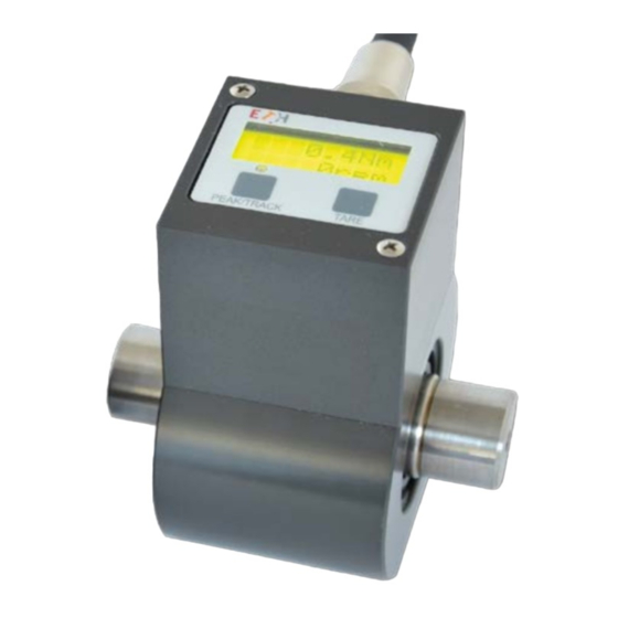
10. Functions of the display (at DRBK-A) The displayed torque is always shown in 4 digits. For example, with a nominal torque of 200 Nm, a value is displayed as „199.2Nm“. The torque is updated every 100ms. The speed is represented as an integer. The valid range is between 0 and 32000 RPM. -
Page 16: Recalibration
The transducer can be returned to us free of charge for disposal, complete with the measuring cable. As soon as this is packed by you, send a message to sales@eth-messtechnik.de, we will then commission our parcel service to collect Unfortunately, we cannot accept parcels sent to us without prior notice. -
Page 17: Datasheet
• Speed indication updated 1x sample/second • Optional speed measurement • Torque updated 1,000 samples/second The Series DRBK torque transducers are suitable for Series DRBK-A torque transducers are custom made lab and industrial applications because of their small for applications where an extra analyzer should not size and multiple mounting options. -
Page 18: Technical Specifications
Technical Specifications: DRBK + DRBK-A 13.1 Technical specifications 11,5 to 28,8 V DC Supply voltage: Current consumption: DRBK approx. 200 mA / DRBK-A approx. 250 mA Rise time 10-90 %: 1 ms 1 kHz Limit frequency –3 dB: Voltage output: 0 to ±... -
Page 19: Mechanical Dimensions Drbk
13.2 Mechanical dimensions DRBK Mechanical Dimensions DRBK 13.3 Sizes DRBK Sizes DRBK Type: I II Torque Ranges: (Nm) | 0,5 | 1 | 2 | | 5 | 10 | 20 | | 50 | 100 | 200 |... -
Page 20: Mechanical Dimensions Drbk-A
Mechanical Dimensions DRBK-A 13.4 Mechanical dimensions DRBK-A 13.5 Sizes DRBK-A Sizes DRBK-A Sizes I II Torque Ranges: (Nm) | 0,5 | 1 | 2 | | 5 | 10 | 20 | | 50 | 100 | 200 |... -
Page 21: Mechanical Values And Load Limits Drbk + Drbk-A
13.6 Mechanical values and load limits DRBK + DRBK-A Technical Specifications DRBK + DRBK-A spring cons- Mass Moment J (g•cm²) Torsion Shaft- Measuring Permitted Permitted Sizes tant C Type range (Nm) Axial load (N) * Radial load (N) *... - Page 22 messtechnik...
- Page 23 messtechnik...
- Page 24 10 D-74417 gschwend tel. +49 (0) 79 72 / 93 10 - 0 fax +49 (0) 79 72 / 93 10 - 50 sales@eth-messtechnik.de www.eth-messtechnik.de BA121_DRBK-DRBK-A_EN_Rev03 | 23. November 2022...
Need help?
Do you have a question about the DRBK and is the answer not in the manual?
Questions and answers