Sign In
Upload
Download
Table of Contents
Contents
Add to my manuals
Delete from my manuals
Share
URL of this page:
HTML Link:
Bookmark this page
Add
Manual will be automatically added to "My Manuals"
Print this page
×
Bookmark added
×
Added to my manuals
Manuals
Brands
WFCO Manuals
Switch
EM-15
Installation & operator's manual
WFCO EM-15 Installation & Operator's Manual
Energy management switch
Hide thumbs
1
Table Of Contents
2
3
4
5
6
7
8
9
10
11
12
13
14
15
16
page
of
16
Go
/
16
Contents
Table of Contents
Troubleshooting
Bookmarks
Table of Contents
Table of Contents
Em-20 Operation
Introduction
Product Description
Modes of Operation
Power Relay Mode
Power Relay Mode W/ Short Delay
Power Relay Mode W/ Long Delay
Logic Relay Mode W/ Short Delay
Logic Relay Mode W/ Long Delay
Remote Control
Remote Panel Functions
Em-20 Installation
Mounting the Enclosure
Mounting to a Wall or Floor
Mounting to a WF-89Xxpec
Mounting to a WF-85Xx
Mounting the EM-20 Remote Control
EM-20 WIRING System Wiring Diagram
Internal EM-15 / EM-20 Wiring
Wiring Instructions
Air Conditioner Logic Wiring for the EM-20
Em-20 Troubleshooting
Specifications
Timing Diagram Example
General Compliance Information
Advertisement
Quick Links
1
Em-20 Operation
2
Em-20 Troubleshooting
Download this manual
Installation & Operator's Manual
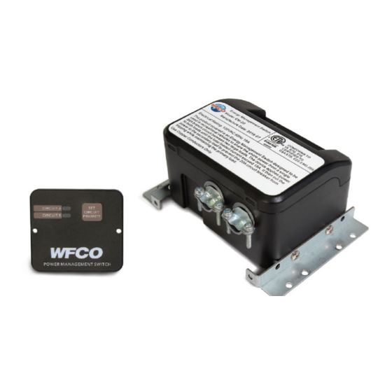
EM-15 / EM-20 Energy Management Switch
WF-9900 Series
Table of
Contents
Previous
Page
Next
Page
1
2
3
4
5
Advertisement
Table of Contents
Need help?
Do you have a question about the EM-15 and is the answer not in the manual?
Ask a question
Questions and answers
Related Manuals for WFCO EM-15
Switch WFCO EM-20 Installation & Operator's Manual
Energy management switch (16 pages)
Switch WFCO T-30 Operator's Manual
Transfer switches (12 pages)
Switch WFCO WF-T30 Product Manual
Transfer switches (18 pages)
This manual is also suitable for:
Em-20
Table of Contents
Print
Rename the bookmark
Delete bookmark?
Delete from my manuals?
Login
Sign In
OR
Sign in with Facebook
Sign in with Google
Upload manual
Upload from disk
Upload from URL


Need help?
Do you have a question about the EM-15 and is the answer not in the manual?
Questions and answers