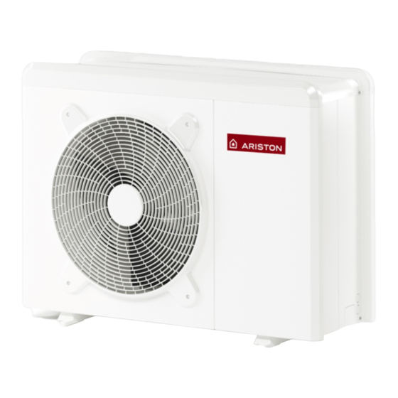
Summary of Contents for Ariston Thermo NIMBUS POCKET M NET
- Page 1 NIMBUS POCKET M NET 3319105 ISTRUZIONI TECNICHE PER L’INSTALLAZIONE E LA MANUTENZIONE TECHNICAL INSTRUCTIONS FOR INSTALLATION AND MAINTENANCE 420000454000...
- Page 2 ELECTRICAL WIRING ATTENTION The electrical connections shall be made after completing all hydraulic connections. The internal and external units must be powered separately according to what is indicated on the tables. Between the internal and external units should also be made a MOD BUS connection. This connection may be made through the use of a cable of reduced section (recommended section 0,75 mm ).
- Page 3 WARNING: Make ground connection prior to any other electrical connections. The internal and external units must be powered separately. To prevent any risk, the power supply cable of the outdoor and indoor unit must only be replaced by the technicians of the after-sales service.
- Page 4 Internal Unit electrical connection Before any operation on the system, turn off the main power. Observe the phase and neutral connections. To access the control panel of the internal unit, proceed as follows: Re- move the three screws (A) indicated in fi gure and remove the cover of the electrical panel (B).
- Page 5 Electrical connections between internal and external unit Before any work on the system, shut off the power at the breaker. 1 ph 3 ph 30mA 30mA EH1 EH1 ST1 ST1 ANODE TA 1 TA 2 TNK BUF +24V AUX 1 NOTE It is strongly recommended to verify the presence of a surge protection device (SPD) on main power line and of circuit breakers connected to the external and internal unit’s control box...
- Page 6 ELECTRICAL SCHEME - BOX OF EXTERNAL UNIT 1 ph 3 ph 61 / GB...
- Page 7 ELECTRICAL SCHEME - LIGHT BOX 1Z BK = Black BN = Brown Green BU = Blue GY = Grey RD = Red WH = White OR - Orange PI - Pink YE = Yellow ENERGY MANAGER YE/GN CN14 YE/GN YE/GN PM AUX ANODE TA 1...
- Page 8 Ariston Thermo SpA Viale Aristide Merloni, 45 60044 Fabriano (AN) Italy Telefono 0732 6011 Fax 0732 602331 info.it@aristonthermo.com...

Need help?
Do you have a question about the NIMBUS POCKET M NET and is the answer not in the manual?
Questions and answers