
Summary of Contents for EKF C20-SATA
- Page 1 Technical Information C20-SATA SATA Dual-Drive Mezzanine Module Document No. 5421 • Ed. 3 • 22 January 2013...
-
Page 2: Table Of Contents
Technical Information C20-SATA • SATA Dual-Drive Mezzanine Module Contents About this Manual ............3 Edition History . -
Page 3: About This Manual
Technical Information C20-SATA • SATA Dual-Drive Mezzanine Module About this Manual This manual is a short form description of the technical aspects of the C20-SATA, required for installation and system integration. It is intended for the advanced user only. Edition History... -
Page 4: Related Documents
Technical Information C20-SATA • SATA Dual-Drive Mezzanine Module Related Documents The C20-SATA is a passive module, intended for use on a suitable active carrier card. For a description of the related carrier board, please consult the associated technical document(s), e.g. -
Page 5: Feature Summary
- consult manufacturers data sheet - SSD recommended for rugged environment Not all of the connectors may be present or functional on your actual C20-SATA board; assembly is highly custom specific. Options may be exclusive, i.e. not necessarily concurrently present. Discuss your needs with EKF before ordering. -
Page 6: Short Description
Technical Information C20-SATA • SATA Dual-Drive Mezzanine Module Short Description Available as a mezzanine add-on storage As an option, the C20-SATA can be populated module to several CPCI side boards, the with another (bottom mount) drive, resulting in purpose of the C20-SATA is to accommodate a 10HP or 12HP assembly stack. -
Page 7: Block Diagram
Technical Information C20-SATA • SATA Dual-Drive Mezzanine Module Block Diagram Option Simplified Block Diagram SATA Cable Header C20-SATA Options High Speed Mezzanine Option Connector SATA SATA Docking Header Docking Header Bottom Mount Top Mount 2.5-Inch 2.5-Inch SATA SATA SATA Solid State Drive... -
Page 8: Top View Component Assembly
Technical Information C20-SATA • SATA Dual-Drive Mezzanine Module Top/Bottom View Component Assembly C20-SATA Top View C20-SATA Bottom View © EKF ekf.com... -
Page 9: Mounting Alternates
Technical Information C20-SATA • SATA Dual-Drive Mezzanine Module Mounting Alternates The C20-SATA will be mounted with a headroom of either 6mm - 10mm - 14mm or 18mm above the carrier board, depending on the number of drives engaged (one or two), the drive height (7.0mm typically for solid state drives, 9.5mm assumed for hard disk drives), and components on the carrier... - Page 10 Technical Information C20-SATA • SATA Dual-Drive Mezzanine Module C20-SATA Assembly Sectional Drawing (South View) SSD/HDD Top Mount 7.0/9.5mm 8mm fem SSD/HDD Bottom Mount 7.0/9.5mm C20-SATA 18.72/ 18.6mm Carrier Board PCB (Side Board) 10mm male Side Board 4HP Pitch 18.72mm nominal 18.6mm hex nut...
- Page 11 Technical Information C20-SATA • SATA Dual-Drive Mezzanine Module C20-SATA Dual Drive Profile View Assembly Stack with C20-SATA © EKF -11- ekf.com...
-
Page 12: Installing And Replacing Components
Store the board only in its original ESD protected packaging. Retain the original packaging (antistatic bag and antistatic box) in case of returning the board to EKF for repair. Typical 4HP Assembly Stack with C20-SATA © EKF -12-... -
Page 13: Installing The Board Assembly
Technical Information C20-SATA • SATA Dual-Drive Mezzanine Module Installing the Board Assembly Warning This procedure should be done only by qualified technical personnel. Disconnect the system from its power source before doing the procedures described here. Failure to disconnect power, or telecommunication links before you open the system or perform any procedures can result in personal injury or equipment damage. -
Page 14: Removing The Board Assembly
Technical Information C20-SATA • SATA Dual-Drive Mezzanine Module Removing the Board Assembly Warning This procedure should be done only by qualified technical personnel. Disconnect the system from its power source before doing the procedures described here. Failure to disconnect power, or telecommunication links before you open the system or perform any procedures can result in personal injury or equipment damage. -
Page 15: Emc Recommendations
Technical Information C20-SATA • SATA Dual-Drive Mezzanine Module EMC Recommendations In order to comply with the CE regulations for EMC, it is mandatory to observe the following rules: The chassis or rack including other boards in use must comply entirely with CE... -
Page 16: Technical Reference - Connectors
Please Note The C20-SATA mezzanine module may be equipped with several connectors for system internal usage. Not all of these connectors may be present on a particular board. Be sure to specify your individual needs when ordering the C20-SATA board. Characteristic features and the pin assignments of each connector are described on the following pages. -
Page 17: I/O Connectors
Technical Information C20-SATA • SATA Dual-Drive Mezzanine Module I/O Connectors The C20-SATA is typically provided with several on-board connectors, prominently the SATA docking header(s). C20-SATA Top View SATA SSD/HDD 2.5-Inch I/O Connectors Docking header for 2.5-inch SATA drive, top mount Docking header for 2.5-inch SATA drive, bottom mount, option... -
Page 18: J2/J3 Sata Docking Header(S)
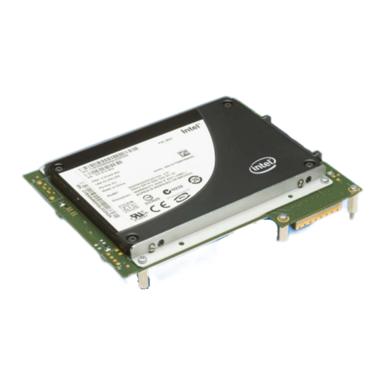
Technical Information C20-SATA • SATA Dual-Drive Mezzanine Module J2/J3 SATA Docking Header(s) The C20-SATA can be equipped with one or two 2.5-inch SATA drive(s), either hard disk (HDD), or silicon state (SSD). The 22-position SATA docking header(s) J2 and J3 allow for direct attachment of the drive(s), without cable assembly. - Page 19 Despite the SATA docking connectors are also provided with reserved pins assigned to +12V and +3.3V, only +5V is required for typical 2.5-inch SATA drives. As a C20-SATA stuffing option, +5V can be derived either from the carrier board, or the connector P2 (for external power supply).
-
Page 20: P1 Sata Cable Header
CPU Board PCB (Base Board) Since P1 is exclusive to J3 (bottom mount drive), P1 is available only in the single drive configuration of the C20-SATA. A right angled cable connector may be used for a minimum height assembly. © EKF -20- ekf.com... -
Page 21: P2 External Power
As of current, 2.5-inch SATA drives require +5V only (P2 pin 1). P2 pin 4 (+12V) can be left open. In rare cases the external power source may deliver +12V only. For this situation the C20-SATA can be provided with an on-board DC/DC switched regulator, from +12V to +5V. -
Page 22: Inter-Board Connector
4HP profile of the carrier board (single drive). Since the C20-SATA comes typically mounted as a unit together with the CPU carrier board, there is normally no need for the user to get access to the inter-board connector. It is described here as a reference only and for better understanding of the C20-SATA. - Page 23 Technical Information C20-SATA • SATA Dual-Drive Mezzanine Module J1 Mezzanine Connector 1.00mm Pitch Female Connector 4mm Height (6mm/14mm Headroom) • 275.90.04.068.01 1.00mm Pitch Female Connector 8mm Height (10mm/18mm Headroom) • 275.90.08.068.01 SATA1 TXP SATA1 TXN SATA1 RXN SATA1 RXP SATA2 TXP...
-
Page 24: Schematics
Complete circuit diagrams for this product are available for customers on request. Signing of a non- disclosure agreement would be needed. Please contact sales@ekf.de for details. EKF reserves the right to refuse distribution of confidential information material for any reason that EKF may consider substantial. - Page 25 Technical Information C20-SATA • SATA Dual-Drive Mezzanine Module © EKF -25- ekf.com...
- Page 26 Technical Information C20-SATA • SATA Dual-Drive Mezzanine Module © EKF -26- ekf.com...
- Page 27 Technical Information C20-SATA • SATA Dual-Drive Mezzanine Module © EKF -27- ekf.com...
- Page 28 Technical Information C20-SATA • SATA Dual-Drive Mezzanine Module Industrial Computers Made in Germany boards. systems. solutions. EKF Elektronik GmbH Phone +49 (0)2381/6890-0 Philipp-Reis-Str. 4 Fax +49 (0)2381/6890-90 59065 Hamm Internet www.ekf.com Germany E-Mail sales@ekf.com...
Need help?
Do you have a question about the C20-SATA and is the answer not in the manual?
Questions and answers