
Subscribe to Our Youtube Channel
Related Manuals for Vinten Osprey Plus S

Summary of Contents for Vinten Osprey Plus S
- Page 1 User Guide Pedestal Studio V4171-0001 OB V4171-0002 Part No. V4171-0001 V4171-0002 www.vinten.com...
- Page 2 Copyright © 2022 All rights reserved. Original Instructions: English All rights reserved throughout the world. No part of this publication may be stored in a retrieval system, transmitted, copied or reproduced in any way, including, but not limited to, photocopy, photograph, magnetic or other record without the prior agreement and permission in writing of the Videndum Group Plc.
-
Page 3: Table Of Contents
Contents Safety..........2 Operation. -
Page 4: Safety
Under no circumstances should the product be used for The Osprey Plus S pedestal is designed for use in television studios the transportation or support of personnel. (OB version field applications) and on location to support and... -
Page 5: Water, Moisture And Dust
Safety Maintenance WARNING! The product must only be operated on a smooth and level surface. WARNING! The fitting of non-approved parts or accessories, or the carrying out of non-approved WARNING! The product must always be secured (all alterations or servicing can be dangerous and could three wheel brakes applied) when left unattended. -
Page 6: About This Guide
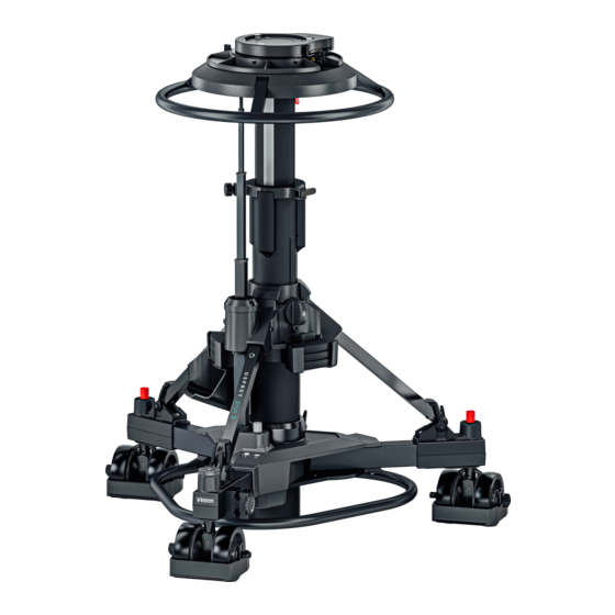
Scan this QR code to access a dedicated page Introduction and Description containing important information: The Osprey Plus S is a fully steerable version of the Osprey Plus and • Safety / educational videos is capable of handling any payload up to 70kg / 155lb. It has 2 stages •... -
Page 7: Components And Connections
Components and Connections Box Contents Item Description Item Description Osprey Plus S Osprey Plus S OB V4171-0001 V4171-0002 Quickfix Quickfix Accessory holder Accessory holder Trim weights x 6 Trim weights x 6 Skid + Studio wheels Skid + OB wheels... - Page 8 Components and Connections Item Description Control valve Four-bolt mounting plate Pressure gauge Steering indicator Top stage Top clamp Bottom stage Safety catch Trim weight stowage Short strut Foot support and strap Wheel brake foot-button Kick bar...
- Page 9 Components and Connections Item Description Skid clamp Trim weight Crab/Steer changeover foot-button Cable guard Cable clamp Tiller socket Fixed strut Bottom clamp Drag control Schrader valve and cap Removable steering ring Steering ring mounting plate Weight tray Accessory holder...
-
Page 10: Optional Accessories
Components and Connections Optional Accessories Item Description Part No. 200mm Hi-Hat with clamp ring (3101-201) 3155-3B 150mm Bowl Adaptor 3330-17 Mitchell head Adaptor with clamp ring (3101-201) 3055-3B Tracking Dolly / Skid 3369-57 100mm Bowl Adaptor 33016 Base Adaptor 08349 PTZ and Prompter plate V4166-1002 Studio Wheels... -
Page 11: Assembling The Pedestal
Installation Assembling the Pedestal Turn the skid upside-down, depress the leg locking plungers and swing each folding leg out until the plungers lock the legs in the fully open position. Fit the kick bar (2), by pressing it into all three sliding catches on the underside of the centre casting (Step 1) and secure it by engaging all three locks (Step 2). -
Page 12: Column
Installation Column Install the column on the skid as follows: Ensure that the rubber straps on each foot support (11) are to the outside of the ball joint. Hold the column uprigh. Raise the struts (20) to about 30° from horizontal. -
Page 13: Pressurizing The Pedestal
Installation Pressurizing the pedestal WARNING! This pedestal must be pressurized only with clean, dry air or nitrogen. A pressure reducing valve must be fitted to the pressure line between the The pedestal may be pressurized using the built-in pump, by using a as cylinder and the outlet connection of the hose. - Page 14 Installation To pressurize the pedestal using the built-in pump, proceed as follows: To pressurize the pedestal manually, proceed as follows: WARNING! Bottom stage elevation is assisted by a gas strut. The bottom stage will rise rapidly if released with no payload fitted. Do not lean over the pedestal when releasing the safety catch and/or the bottom clamp Set the control valve (1) to the PUMP position.
- Page 15 Installation WARNING! A pressurized pedestal will rise rapidly if the control valve is set to WORK. Do not move the control valve directly from PUMP to WORK. Push the control valve (1) in and turn 90° counter clockwise to the Push the control valve (1) in and turn 90°...
-
Page 16: Pressurizing The Pedestal Using A Portable Pump
Always restrain the pedestal by hand pressure on the steering ring when the safety catch is released. To pressurize the pedestal using the Vinten portable *pump, proceed as follows: Attach the intended payload, see Fitting and balancing the load on page 16 Set the control valve (1) to the WORK position. -
Page 17: Pressurizing From An External Pressure Source
Installation Pressurizing from an external pressure source WARNING! This pedestal must be pressurized only with clean, dry air or nitrogen. A pressure reducing valve must be fitted to the pressure line between the gas cylinder and the outlet connection of the hose. The reducing valve must be screwed into the gas cylinder outlet. -
Page 18: Fitting And Balancing The Load
The pedestal has the standard four-bolt mounting plate which permits operates. the use of various Vinten camera mounts including pan and tilt heads, Quickfix and Mitchell adapters See Optional Accessories on page To remove a head Push up the red... - Page 19 Installation Fit the adaptor to the ped first, then the head followed by the camera, blue indicates moving parts not assembly sequence. Once the head is fitted follow head and accessories manuals to securely fit all of he payload (which may include camera, lens, teleprompter, viewfinder and accessories.
-
Page 20: Operation
Operation Height adjustment Lower stage pressure-assistance is provided by a gas strut located within the column. The strut is available in three pressure settings (See below) and the correct one should be installed according to the pedestal load. (See Replacing gas struts on page 28). -
Page 21: Top Stage
Operation Top stage Brakes The top stage of the column has an on-shot stroke of 420 mm (16.5 Each of the skid wheels is fitted with a in.) and the load can be moved over this distance, in perfect balance, foot operated brake. -
Page 22: Pedestal Movement
Operation Pedestal movement Pushing the foot-button (16) operates a changeover mechanism which toggles the pedestal between crab and steer. The button can be pressed with the wheels in any position, but the changeover will Directional control of the pedestal is achieved by turning the steering not occur until the wheels are all facing forward, so the steering ring mounted at the top of the column. -
Page 23: Steering Tiller
Operation Steering Tiller The steering tiller (Part No.3329-21) provides an alternative means of steering the skid. It is particularly useful when the skid is fitted with a head-to-skid adapter or fixed column, or when a grip is required to manoeuvre the pedestal. The tiller is fitted as follows: Unscrew and remove the round cap which is fitted on the tiller Steering... -
Page 24: Changing The Skid Tracking Width
Operation Changing the skid tracking width WARNING! To ensure maximum stability when the skid is set to narrow track, particularly when moving over The movable skid legs can be set to either of two positions. 1: Wide uneven ground, reduce pedestal height to a minimum for normal use, maximum stability. -
Page 25: Optional Wheels
Operation Optional wheels To replace the wheels: Remove the column from the skid (see Transportation and storage A set of 160 mm (6.3 in.) wheels (Part No. 3329-30) is available to on page 24( and turn the skid upside down. convert the skid from studio to OB use. -
Page 26: Transportation And Storage
Operation WARNING! Local, national or international regulations may apply to the transport and storage of pressurized pedestals. NOTE: It is not necessary to reduce the pedestal pressure prior to transportation or storage. To avoid the possibility of dust or abrasive particles collecting on moving components, set the column to minimum height. Transportation and storage Lower the top stage (5), then set the control valve to PUMP Remove the load and secure any trim weights (15) in the... -
Page 27: Maintenance
Operation Set the safety catch slide (8) to LOCK position (I) and fully depress both columns until the safety catch engages and tighten the bottom clamp (3). Release the skid clamp (14). Release the three rubber foot straps (11) from the struts. Raise each strut. -
Page 28: Servicing
Maintenance Servicing Routine Maintenance The Osprey requires minimal routine maintenance, apart from General checking the connections and overall operation periodically. The Osprey pedestal is robustly made to high engineering standards Check the following points during normal use: and little attention is required to maintain serviceability except for regular cleaning. -
Page 29: Bottom Clamp Adjustment
Maintenance Bottom clamp adjustment When the bottom clamp is correctly adjusted, the V notch on the Remove the knob and turn the spindle (5) clockwise until finger-tight. bottom clamp knob (4) should be just before the 12 o’clock (vertically Replace the knob (4) on the spindle (5) so that the ‘V’ notch on the upwards) position when the clamp is fully applied. -
Page 30: Skid Clamp Adjustment
Maintenance Skid clamp adjustment Replacing gas struts The top clamp is applied by pulling the flip lever out. The skid clamp Bottom stage elevation assistance is provided by a gas strut located is applied and released by turning the handle clockwise or counter- in the telescopic column. - Page 31 Maintenance Remove the load, release the bottom clamp (21) and set the bottom Unscrew and remove the centre end plug (23) from the base of the stage (7) to its maximum height. Both stages must be fully telescopic column. extended and the payload removed. Withdraw the gas strut (24) from the column.
-
Page 32: Technical Specification
Technical Specification Physical Data (Studio V4171-0001) Physical Data (OB V4171-0002) Minimum height Tracking Width Minimum height Tracking Width 670 mm (26.4 in.) 970 mm (38.2 in.) 695 mm (27.4 in.) 940 mm (37 in.) Maximum height Doorway Tracking Width Maximum height Doorway Tracking Width 1480 mm (58.3 in.) 730 mm (28.7 in.) - Page 33 Environmental Data Operating temperature range +5°C to +40°C (41°F to +104°F) Storage temperature range -20°C to +60°C (-4°F to +140°F) Technical specifications are subject to change without notice.
-
Page 34: General Notices
General Notices General Notices EU Declaration of Conformity Videndum Production Solutions Ltd. declares under our sole responsibility, supported by Videndum Production Solutions GmbH - our authorized representative, that the product detailed in this manual conforms with all relevant provisions of the following EU directives: Machinery Directive 2006/42/EC A copy of the declaration is available on request. - Page 35 General Notices General Notices Environmental considerations European Union Waste of Electrical and Electronic Equipment (WEEE) Directive (2002/96/EC) This symbol marked on the product or its packaging indicates that this product must not be disposed of with general household waste. In some countries or European Community regions separate collection systems have been set up to handle the recycling of electrical and electronic waste products.
- Page 36 Publication No. V4171-4980/0 www.videndum.com...
Need help?
Do you have a question about the Osprey Plus S and is the answer not in the manual?
Questions and answers