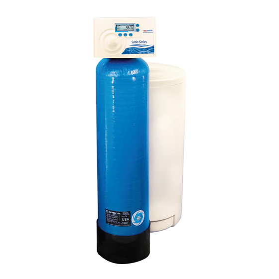
Summary of Contents for Master Water Conditioning MCA Series
- Page 1 MASTER Water Conditioning Corp. Installation and Operation Manual MCA Time Clock Series Residential Softeners February 2011 Version...
- Page 2 Table of Contents Page Topic Description Model # and Packaging Packaging Information Component Packaging Packaging Description Description Softening System System Positioning MCA Control Valve Attaching Valve to Tank MCA Control Valve Attaching Valve, cont’d Service & Drain Piping Drain Piping Service &...
- Page 3 Installation and Operating Instructions for MCA CONTROL Top Mount Water Softener Model #: _______ MCA-30T 1.0 CF Water Softener _______ MCA-45T 1.5 CF Water Softener _______ MCA-60T 2 CF Water Softener _______ MCA-75T 2.5 CF Water Softener Shipping Carton Description / unit: # of Contents Description...
- Page 4 Water Softener Positioning: 1. Place water softener in desired position, far enough from walls and other obstructions to allow for servicing the unit. 2. Place the water softener within reasonable access to a grounded 115V/60 HZ circuit and a legal drain line connection. MCA Control Valve: 1.
- Page 5 valve. Align the insert connection ends with o’ring seals and nuts to the inlet and outlet connections of the control valve. Hand tighten the nuts. DO NOT OVERTIGHTEN THE NUT! Bypass Valve Control Valve Tail piece assembly 6. Locate the tail piece kit that is packaged with the control valve. The standard tail piece kit is 1”...
- Page 6 install a ¾” union on the drain line for servicing if not using 5/8 OD. The drain line must be of adequate size to allow for full regeneration flow. DRAIN LINE CONNECTION • The control valve drain connection is 5/8 OD or 3/4" npt.
- Page 7 MASTER Water Conditioning Corp. TYPICAL PIPING LAYOUT FOR MCA SERIES SOFTENER Treated Air Gap Drain Master Water Conditioner Well Tank Brine tank Overflow fitting to floor drain gravity NOTE: All Master Water Conditioners must be installed after the well tank or water meter if its...
- Page 8 Electrical Requirements: Always follow all local electrical codes when installing our water treatment equipment. 1. Provide an 115v/60Hz properly grounded dedicated electrical Outlet. (It’s very important that the polarity be correct) Avoid using outlets that are switch controlled. 2. Maximum amperage required is 5 amps. 3.
- Page 9 Filling Water Softener with Water: 1. Connect the MCA control valve transformer into the electrical outlet provided. 2. Press and hold the Up and Down arrows simultaneously for three seconds until the drive motor starts. When the drive motor stops, the display will read “C1”...
- Page 10 MCA Control Valve Timer Settings: Note: The control valve is set at the factory. You only need to set the time of day and regeneration time if required, which is preset at 2 am. Time of Day Setting 1) Press and hold the CLOCK button. The screen will display “Set Time”...
- Page 11 Final Check: 1. Fill the brine tank with Solar Salt and the Res-Up Feeders with Res- Up (one quart is provided). 2. Make sure the drain line connection meets all plumbing codes and that the drain line size can handle the backwash flow rate of the softener.
- Page 13 Troubleshooting Problem: Water conditioner fails to regenerate. No soft water. Possible Cause Solution Power supply to MCA control has Determine reason for power been interrupted. interruption and correct. Reset time of day. Water pressure lost. Restore water pressure. Corrupted programming of MCA Reprogram timer assembly.
- Page 14 Problem: Insufficient brine draw Possible Cause Solution Partially clogged injector or injector Inspect and clean injector and/or screen. injector screen assembly. Restricted flow rate in brine line. Check flow rate capabilities of the safety float/aircheck assembly. Insufficient water pressure. Increase water pressure above 25 psig (172kPa) minimum.
- Page 15 Problem: Leak to Drain Possible Cause Solution No flow control installed in drain Install drain line flow control. line. Insufficient water pressure. Increase water pressure above 25 psig (172kPa) minimum. Damaged piston and/or piston Inspect and if damaged, replace stock parts. piston and/or piston stock parts Problem: Loss of Water Pressure Possible Cause...
- Page 16 Problem: Timer does not display time of day Possible Cause Solution AC Adapter unplugged Connect power No electric power at outlet Repair outlet or use working outlet Defective AC Adapter Replace AC Adapter Defective PC Board Replace PC Board Problem: Timer does not display correct time of day Possible Cause Solution Switched outlet...
- Page 17 Problem: Control valve does not regenerate automatically when UP and DOWN buttons are held and depressed Possible Cause Solution AC adapter unplugged Connect AC adapter No electric power at outlet Repair outlet or use working outlet Broken drive gear or drive cap Replace drive gear assembly assembly Defective PC board...
- Page 18 ERROR CODES Display Description Cause Unable to recognize start of Defective motor, damaged E1 (1001) regeneration wiring, or poor wire connection. Unexpected electrical or Defective motor, damaged E2 (1002) mechanical stall wiring, poor wire connection, or mechanical component failure. Motor running too long or Damaged wiring, poor wire E3 (1003) timeout during piston relocating...
- Page 24 All claims must be submitted in writing to Master Water Conditioning Corporation at 224 Shoemaker Road, Pottstown, Pennsylvania 19464 within thirty (30) days from the discovery of the defect.


Need help?
Do you have a question about the MCA Series and is the answer not in the manual?
Questions and answers