
Related Manuals for FlySky Noble Pro


Summary of Contents for FlySky Noble Pro
- Page 1 USER MANUAL USER MANUAL Touching Infinity Copyright ©2022 Flysky Technology co., ltd Website...
- Page 2 Read the manual carefully to ensure your personal safety as well as the safety of your equipment. If you encounter any problems during using, please refer to this manual first. If the problem is still not resolved, please contact the local dealer directly or contact the customer service staff via the website below: www.flysky-cn.com...
-
Page 3: Table Of Contents
Catalog 1. Safety............................1 1.1 Safety Symbols ...............................1 1.2 Safety Guide................................1 2. Product Introduction.........................2 2.1System Features ..............................2 2.2Transmitter Overview .............................3 2.3 Receiver Overview ..............................6 2.3.1 Status Indicator ..............................6 3. Getting started..........................7 3.1 Transmitter Battery Installatin ..........................7 4. Operation Instruction........................8 4.1 Power On ................................8 4.2 Binding ...................................8 4.3 Transmitter LED Indicator............................8 4.4 Power Off ................................8... - Page 4 8.10 Stick Calibration ..............................42 8.11 FirmWare Update ...............................42 8.12 Factory Reset ..............................42 8.13 About Noble Pro..............................42 9. Product Specifications ......................43 9.1 Transmitter Specification (Noble Pro) ......................43 9.2 Receiver Specification (FGr4B) ..........................44 9.3 Receiver Specification (FGr8B) ..........................44 10. Packing List .........................45 11. Instructions ..........................46 11.1 Brake Pad Replacement and Angle Adjustment ....................46...
-
Page 5: Safety
1. Safety 1.1 Safety Symbols Pay close attention to the following symbols and their meanings. Failure to follow these warnings could cause damage, injury or death. Danger • Not following these instructions may lead to serious injuries or death. Warning •... -
Page 6: Product Introduction
FGr8B receiver, and FGr4B receiver. It supports output in 18 channels. In addition, the product implements extreme-speed output on 2 channels. A cell phone holder with Noble Pro is more convenient for users to perform monitoring in real time. It is also compatible with model cars, boats, and etc. -
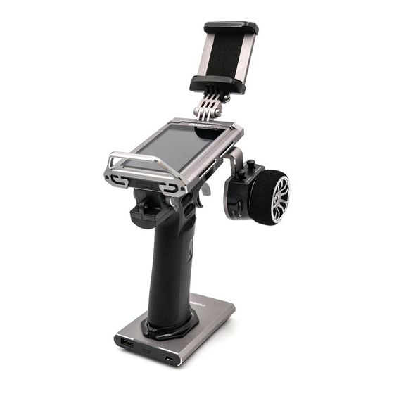
Page 7: Transmitter Overview
2.2 Transmitter Overview Cell phone holder Wheel Forced shutdown button (placed at the bottom of the grip) Battery Note: If you can't shut down the transmitter properly, Please shut down the transmitter by pressing the force shutdown button on the transmitter. (Operation: pull the hand glue placed at the top of transmitter's grip or take off the whole handle glue. - Page 8 Holder connection hole Lanyard Eye Grip Trigger spring adjsustment Trigger size adjustment Battery Port USB Port (Charging), Update program, and connect the simulator interface. Power Button USB 5V 2A (Power Out) Base power button: Press for a short time to charge the battery at the transmitter handle and to charge external devices.
- Page 9 Adjustable Screen TR2 Trim TR1 Trim RGB LED Power Button Wheel Adjust the length of the cell phone holder Wheel Tension Adjustment Screw Trigger Position Adjustment Screw Website...
-
Page 10: Receiver Overview
2.3 Receiver Overview NPA/8 VCC/BVD NPC/6 NPD/5 Antenna Bind NPB/7 FGr8B VCC/BVD Bind CH4(NPA) Antenna CH3(NPB) CH2(NPC) CH1(NPD) FGr4B For best signal quality,it is recommended to keep the receiver antenna up and away from metal when installing the FGr8B or FGr4B receivers. 2.3.1 Status Indicator The status indicator is used to indicate the power and working status of the receiver. -
Page 11: Getting Started
• Do not use the battery if damaged. The Noble Pro has 2 batteries, one located in the handle and one in the removeable base. To attach the base: 1. Line up the base so that the transmitter handle has a slight over hang on the back. -
Page 12: Operation Instruction
Check to make sure everything functions as expected. If not repeat the steps above. • This binding procedure only applies to the Noble Pro transmitter and FGr8B/FGr4B receivers. Different receivers have different binding procedures. Please refer to our official website for more information and relevant user manuals. -
Page 13: System Interface
5. System Interface The main interface mainly displays information related to the model, such as transmitter voltage information, function status and so on. The display on the main interface can be customized as required, including the states and data of the main interface. -
Page 14: Function Settings
6. Function Settings This section details functions and their use. 6.1 REV The Reverse function is used to correct a servo or motor's direction in relation to the systems controls. For example, if a steering servo is mounted upside down in order to fit inside a model, when the system's steering wheel is turned, the servo will move in the opposite direction. -
Page 15: St Dr/Exp
6.4 ST DR/EXP This function changes the steering channel's response curve. There are 2 main parameters: [Rate]: Changes the outer limits of the steering, the default and maximum is 100%. [Exp]: Changes the steering curve, which changes the response of the steering wheel. The Exp. -
Page 16: Timer
6.6 Timer This function can set with a variety of timers, to generally calculate the total model run time, competition specific time spent, or transmitter run time, etc. The timer function can be activated in three modes: Mode 1: 1.Click the [Timer Mode: Up Timer] icon. Click the right side of the corresponding function as needed. -
Page 17: Assign
6.7 ASSIGN This function assigns the system's physical buttons to different functions for quick control. A key/ switch or knob can be assigned to control multiple functions or auxiliary channels at the same time. The six keys or knobs (TR1-FB, TR1-LR, TR2-FB, TR2-LR, TR3, and TR4) have the same function and can be used to quickly adjust the values of CH3 to CH18 and multiple functions, with assigning 2-position or 3-position switches. - Page 18 The functions of VR1-L and VR1-R are the same as above. However, the step is not adjustable. The keys of SW1L, SW1R, SW2 and SW3 can be used to control the enabling, disabling, or switching of channel 3 to channel 18, as well as multiple functions. The combination of SW2 and SW3 are used to adjust the values of the selected channels and functions.
-
Page 19: Aux
6.8 AUX Noble Pro has two fixed channels. Channel 1 outputs steering and channel 2 outputs throttle. If you need to increase the fixed channel, you can use this function. Channel name pre-selection: 1. Click [CH5] or other channels to enter the interface to set the channel name. - Page 20 Noble Pro's keys or knobs can be used to control the enabling, disabling, or switching of channel 3 to channel 18, as well as multiple functions. The 2-position or 3-position switch can be assigned. Alternatively, the value can be used for adjusting the speed.
-
Page 21: Model
[Select Model]: To select a model touch "Select Model", then touch a model from the list. [Name: FlySky 01]: After clicking, use the keyboard in the interface to type in a new name. [Channel Number Definition]: this function is used to select the number of channels. If the larger number of channels is switched to the lower number of channels, the system will prompt "After switching you need re-binding,... - Page 22 [Import or Export Model] : You can import and export models by logging in to the FlySky official website to download the software (FlySky Assistant) and then operate it on the PC (No need go back to click the menu on the...
-
Page 23: Sensor
6.10 Sensor This list shows all sensors connected to the receiver, including sensor type, number and real-time data.This list can also be accessed quickly from the home screen. [Display Sensors]: This list shows all sensors connected to the receiver, including sensor type, number and real-time data. - Page 24 Speed sensor (FS-CPD01, FS-CPD02) The speed sensor is applied to test the speed of the motor. • "Motor speed" indicates that the sensor is testing the motor speed; Sensor "0rpm" is the speed measurement value. Magnetic induction speed sensor (FS-CPD01) Wheel magnet 1.
-
Page 25: Speed
6.11 CH SPEED This function allows you to set the steering speed, forward speed, brake speed and response speeds of CH3 to CH18. Note: the number of channels controlled is subject to the [Channel Number Definition]. [Steering Speed]: changes the corresponding speed of the servo when the steering channel is outputting at fast speed. - Page 26 Channel speed - Front/Throttle This function is used to set the delay of the throttle start and return-to-center. [Start]: sets the speed of throttle acceleration. [Return to center]: sets the speed at which the throttle returns to the center position. [Point P1]: means the division point between the first forward travel and the second forward travel.
-
Page 27: Mixes
6.12 MIXES This function allows you to set 5 mixing functions, that is, [4WS Mixing], [Track Mixing], [Drive Mixing], [Brake Mixing], and [Programming Mixes]. 4WS Mixing Used to set the wheels that control steering of the vehicle, front, rear or all four wheels. This function is applicable to crawler with steering on both front and rear wheels. - Page 28 Drive Mix Drive mix is used to set the way to control the vehicle engine drive, including three drive modes: rear drive, front and rear hybrid drive, and front drive. By default, rear drive is used. Front drive has a shorter braking distance, which is suitable for emergency braking. In rear drive, the front wheels can focus on steering, which is more suitable for vehicle drift.
-
Page 29: Abs
Programming Mixes The Mixing function can be used to set the mix-control relationship between channels, containing a total of 8 groups of mixing relationships. Setup: 1. Click [Mixing 1] or other mixing options as needed to enter the setting interface. 2.Click the icon to enable this function. - Page 30 Delay Determines how long it takes for the A.B.S. system to take effect. At a setting of 0%, the A.B.S. system will take effect as soon as the brake is applied. The higher the value, the longer it will take for the A.B.S. to function. When set to 0% there will be no delay, meaning the breaks will be applied as soon as they are triggered.
-
Page 31: Throttle Middle
4. Repeat as needed. 5. Test to make sure everything is working as expected. 6.14 Throttle Middle The throttle middle function is used to set the neutral position of the throttle and brake to correct the problem of unequal throttle travel and brake travel of some models. If the neutral position is not set correctly, the model may start acceleration and driving directly after power-on. -
Page 32: Eng Cut
to keep it from stalling. This function must be assigned to a switch/button in order to be activated . This function will reset after shutting down. Restart this function after turning on again. Setup: Click the icon to enable this function. When this function is enabled, the icon will change to 2.The system jumps to the [Key Setting] function (please refer to [6.8 Key Setting] function... - Page 33 [Neutral Calibration]: Used for gyroscope to calibrate steering and throttle neutral to make the best driving condition when the vehicle is driving normally. • Before enabling the intelligent vehicle control function, you need to adjust the vehicle's steering servo volume, neutral trim and throttle neutral to the best driving condition. After completion, start the [Smart Vehicle Control] function for neutral calibration.
-
Page 34: Boat
This function provides the QR code of the product manual and the QR code of Skyfly promotion platform, including the official website, WeChat public account, and advertising site at www.flysky-cn.com. Users can obtain the QR code and scan it as required. Website... -
Page 35: Rx Set
7.1 Bind Set This function is used to adjust the transmitter to the bind state so that it can bind with the receiver. Noble Pro supports a dual-receiver mode. The ex-factory bind settings of the transmitter and receiver are completed successfully. -
Page 36: Steering Force
Noble Pro's [Two Receiver Mode] function. Noble Pro has only 18 output channels. When the number of combined dual receiver channels exceeds the number of channels pre-selected by the transmitter, extra channels cannot be used. -
Page 37: Rx Interface Protocol
7.4 RX Interface Protocol This function is used to set the receiver output mode. When the adapted receiver is FGr4, FGr4S, FGr4P, FTr4, FTr10 and FTr16S, [Output] can be set to PWM or PPM. [Serial Protocol] can be set to i-BUS or S.BUS (please refer to [7.5 i-BUS Setting] for specific i-BUS setting). -
Page 38: Failsafe
To connect to the enhanced receiver: [SR]: one of the specifications in the servo response speed (PWM frequency is 833 Hz). [SFR]: one of the specifications in the servo response speed (PWM frequency is 1000 Hz). [Synchronization with radio frequency]: the digital signal of low frequency is synchronized with the digital signal of radio frequency. -
Page 39: I-Bus2 Setup
7.7 i-BUS2 Setup This function is used to set up the i-BUS2 devices, such as FS-iBH07 Hub or servos with i-BUS2 protocol. • Firstly at the transmitter side, set the receiver interface connected to the hub to i-BUS2 via [RX interface protocol] function. -
Page 40: Config Pwm Converter
7.9 Config PWM Converter This function allows you to configure the corresponding receiver to a PWM converter (hereinafter referred to as a secondary receiver). Setup: Note: Shut down the receiver. 1. Set the receiver to the bind state. 2. Turn on the transmitter. Enter the [Config PWM Converter] menu. Click the right side of [i-BUS to PWM].This function allows you to configure the corresponding receiver to a PWM converter (hereinafter referred to as a secondary... -
Page 41: Bvd Voltage Calibration
7.12 BVD Voltage Calibration The BVD voltage is calibrated in the post-factory settings. This function can be used to calibrate when there is a large deviation between the detected voltage and the actual voltage.The BVD voltage value can be adjusted in the range of 0 to 100 V. Setup: Connect the BVD detection line correctly before setting, and then perform calibration. -
Page 42: Update Receiver
Touch [Update Receiver]: • Some receivers such as GMr need to be updated with "Flysky Assistant". If the transmitter has successfully coded and the connection is established, if the receiver is the latest version, a pop-up prompt will appear [The current version is the new version, no upgrade is required! ]. -
Page 43: System
8 SYSTEM 8.1 Units Choose what units to use for length and temperature. Choose what units to use for length and temperature. [Length] can select metric and imperial system. The default is metric. [Temperature] can be selected in Celsius and Fahrenheit. The default is Celsius. The box highlighted in light green is the currently selected setting. -
Page 44: Sound
8.3 Sound This function is used to toggle all system sounds, including alarm sound, power-on/ power-off sounds and and adjust the volume. [Volume]: Touch volume then select the desired volume from the list. Touch the back icon to return to the previous menu. [System sound]: Click the option box on the right side of the interface. -
Page 45: Home-Screen Quick Access
8.6 Home-Screen Quick Access This function is used to set up the Up, Down, Left and Right quick sliding screen functions of the main interface. Users can customize the sliding screen interface according to their needs. The [Home-Screen Quick Access] can help users find setting interfaces quickly. For example, when users want to check the lap counting time after the function is enabled in the model operations, users can use this function to enter the timer interface quickly. -
Page 46: Stick Calibration
Touch "Factory Reset", then touch "YES" when prompted. Tips: to avoid mis-operations, please do not use this function. 8.13 About Noble Pro This function contains basic information such as product name, firmware version, version date, hardware and RF library version. -
Page 47: Product Specifications
9. Product Specification This chapter includes specifications for Noble Pro transmitters, FGr8B receivers and FGr4S receivers. 9.1 Transmitter Specification (Noble Pro) Product model NB4 Pro Product name Noble Pro Channels 2 ( Fast) 、 4 、 6、 8、 10、 12、 18 Optional... -
Page 48: Receiver Specification (Fgr4B)
9.2 Receiver Specification (FGr4B) Product model FGr4B 2.4GHz ISM 2.4GHz ISM Protocol AFHDS 3 Suitable transmitters Suitable for all transmitters supporting the AFHDS3 Antenna Type single antenna Power 3.5-9V Data port PWM/PPM/i-Bus/s.bus/i-Bus2 Temperature range -10℃—+60℃ Humidity Range 20%-95% Online Update Size 17*29*16.6mm Weight... -
Page 49: Packing List
10.Packing List Serial Packing Name Quantity Remarks number method Noble Pro transmitter Control box Contains the mobile phone holder, base FGr4B receiver Static bag Includes instruction sheet and BVD cable FGr8B receiver Static bag Includes instruction sheet and BVD cable... -
Page 50: Instructions
11. Instructions 11.1 Brake Pad Replacement and Angle Adjustment Turn the hexagonal screwdriver First insert a hexagonal screwdriver into the counterclockwise until the screw is screw hole used to secure the steering wheel. completely loose and remove it. Pinch the brake pad with two fingers and take Take out the steering wheel upward. - Page 51 Place the tube of the steering wheel in the Insert the screw into the screw hole used brake pad adjustment hole on the protruding to secure the steering wheel, then align the connector on the brake pad, and press the hexagonal screwdriver with the hexagonal steering wheel to fix it.
-
Page 52: Installation Of Mobile Phone Holder
11.2 Installation of Mobile Phone Holder Insert the screws into the screw holes Face the installed holder shell handle upward on both sides of the bottom holder shell. and align both sides of the holder shell with both Connect the left and right sides of the sides of the transmitter display screen. -
Page 53: Disassembly Of Mobile Phone Holder
Connect the phone holder to the other end of the holder connector. Align the connection hole and insert the long Ensure the holder connector is screw. Set the nut on the other end of the screw and installed. gently install the nut clockwise by hand to make it fixed. After installation, twist the holder to ensure the holder is flexible and is firmly fixed. - Page 54 Gently unscrew the nut connecting the holder connector and the holder shell counterclockwise by hand until the nut is completely loose. Then remove the screw, nut and holder. Use a screwdriver to connect the screws on both sides of the top of the screen. Gently turn the screwdriver counterclockwise until the screws on both sides are completely loose.
-
Page 55: Wireless Charging Function And Precautions
11.4 Wireless Charging Function and Precautions Wired Charging Method The transmitter base can be charged directly by connecting the USB data cable. Wireless Charging Method • The four bumps of the transmitter base should be connected to the base of the wireless charging transmitter. •... -
Page 56: Replacing Vr1 Knob As A Three-Position Switch
11.5 Replacing VR1 Knob as a Three-position Switch Turn the knob clockwise until the knob is loose. Pinch the knob with the thumb and Make sure that the knob needs to be replaced index finger and then lift it upward to remove with a three-position switch. -
Page 57: Replacing The 3-Position Switch As Vr1 Knob
11.6 Replacing the 3-position Switch as VR1 Knob Remove the three-position switch upwardly. Align the knob with the potentiometer handle cap and press down hard on the knob until the knob is completely fixed. Website... -
Page 58: Certification
12. Certification 12.1 DoC Declaration Hereby, [Flysky Technology co., ltd] declares that the Radio Equipment [Noble pro(Noble Pro] is in compliance with RED 2014/53/EU. The full text of the EU DoC is available at the following internet address: www.flysky-cn.com 12.2 CE Warning The antenna(s) used for this transmitter must be installed to provide a separation distance of at least 20 cm from all persons and must not be co-located or operating in conjunction with any other transmitter. -
Page 59: Appendix 1 Fcc Statement
Appendix 1 FCC Statement 12.4 This equipment has been tested and found to comply with the limits for a Class B digital device pursuant to part 15 of the FCC rules. These limits are designed to provide reasonable protection against harmful interference in a residential installation. - Page 60 Copyright ©2022 Flysky Technology co., ltd Release date: 2022-08-13 Website FCC ID: N4ZFG400 Manufacturer: ShenZhen FLYSKY Technology Co., Ltd Address: 16F, Huafeng Building, No. 6006 Shennan Road, Futian District, Shenzhen, Guangdong, China...
Need help?
Do you have a question about the Noble Pro and is the answer not in the manual?
Questions and answers