
Summary of Contents for MB 700 Series
- Page 1 MBSoiling Station– 700 Series Advanced Soiling Station Series Document ID: M4 028 010 010 01 (R2) Revision 1.03 2022/05/29 SW 2.10...
-
Page 2: Table Of Contents
Table of Contents Warnings ..............................5 MBSoiling Station ........................... 6 MBSoiling Station Applications ......................6 Soiling Parameters ......................... 6 MBSoiling Station Models ......................7 MBSoiling Station Installation ........................ 9 MBSoiling Station With Solar Charger: ..................9 MBSoiling Station – Without Solar Charger: ................11 MBSoiling Station - Cleaning: .......................12 MBSoiling Station Controller Connections ...................13 3.4.1 PV Panel Interface ........................13... - Page 3 Configure – Cellular Modem .......................35 Configure – Serial Port (RS485) ....................35 Configure – ETH Network ......................38 4.10 Configure – SNTP Client ......................39 4.11 MyPage Parameters ........................40 4.12 User Configuration ........................41 4.13 Commit Configuration .........................41 4.14 Embedded Webserver– Diagnostics .....................43 MBSoiling Station Status ......................44 5.1.1 MBSoiling Station Status ......................44 Soiling Station Modem Status ..................45...
- Page 4 My Parameters ..........................60 Soiling Parameters ........................61 Measurement Panel Parameters ....................61 Soiling Station Diagnostics ........................64 Soiling Station Library ...........................67 10.1. Library for Solar Panels .........................67 Revision History ............................68...
-
Page 5: Warnings
Warnings • Installation at site should be done by skilled and qualified personal after taking required approvals. • Use proper protection gear and tool while installing the device. • Be aware of your surroundings while doing the installation work. • Serious injury can occur if proper safety norms are not followed. -
Page 6: Mbsoiling Station
MBSoiling Station MBSoiling Station series-700is advanced range of soiling station. The soiling station provides following advanced functions: 3. Uses latest ARM 32 bits processor. 4. Real time monitoring of clean and soiled PV panels. 5. Regular monitoring and filtering of soiling parameters. 6. -
Page 7: Mbsoiling Station Models
Soiled Panel Voltage Soiled Panel open circuit voltage Soiled Panel Current Soiled Panel short circuit current Soiled Panel Temperature Soiled Panel temperature Calculated based on panel short circuit current and panel temperature for Reference panel Effective reference panel. Irradiation - EffRadClean This calculation also compensates for the panel temperature and the panel temperature coefficient. - Page 8 M: Soiling station with modem H: Soiling station with high wattage solar panel...
-
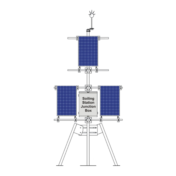
Page 9: Mbsoiling Station Installation
MBSoiling Station Installation MBSoiling Station connections are described in this section. All connections described here may not be available in your soiling station. Features and connections available will depend on the model selected. 3.1 MBSoiling Station With Solar Charger: Soiling station can be powered via solar PV panel or AC power supply. Diagram for soiling station is shown in figure 3.1 below. - Page 10 Galvanised- for installing Measurement panels measurement solar panels along boom Pipes with mounting accessories. Panel Clean Clean solar panel Panel Soiled Soiled solar panel Temperature sensor MBMet-801B-3000 PT1000 with three meters cable – clean panel Temperature sensor MBMet-801B-3000 PT1000 with three meters cable –...
-
Page 11: Mbsoiling Station - Without Solar Charger
MBSoiling Station – Without Solar Charger: Diagram for soiling station without solar charger is shown in figure 3.2 below. Fig - 3.2 Soiling station without solar charger Parts of soling station without solar charger are listed in table-3.2 below. Part Model Description Soiling Station... -
Page 12: Mbsoiling Station - Cleaning
25x2.5mm – Five Copper strip For earthing lightening arrestor meters Cables Required interconnecting cables Soiling Station Control Box Soiling station MBMet- Soiling station controller as per controller 700X selected model Enclosure IP65 Enclosure mounting accessories Power supply and serial port protection devices Table- 3.2: Soiling station without solar charger 3.3 MBSoiling Station - Cleaning:... -
Page 13: Mbsoiling Station Controller Connections
MBSoiling Station Controller Connections Soling station controller connections are explained here. 3.4.1 PV Panel Interface Connections for clean and soiled solar panels are shown in figure -3.4.1 below. Figure-3.4.1: Clean and soiled panel connections Details of measurement PV panels connections are provided below in table 3.4.1. Wire Terminal Description... -
Page 14: Mbsoiling Station Power Supply Connections
3.4.2 MBSoiling Station Power Supply Connections Soiling station controller power supply connections are shown in figure 3.4.2 below. These terminals are not plugin type. Figure-3.4.2: Soiling station controller power supply connections. Power supply connections details are listed in table-3.4.2 below. Terminal Wire Colour Function... -
Page 15: Serial Port -Rs485
3.4.3 Serial Port -RS485 Soiling station serial port - RS485 are shown in figure 3.4.3 below. This port can be used only as MODBUS slave to read soling parameters. Figure-3.4.3: Soiling station serial port-1 (RS485) connections. Note: Serial port-2 is not used. Connection details for the serial port are listed in table-3.4.3.1 below. -
Page 16: Port Eth
These parameters can be changed via the embedded web server. 3.4.4 Port ETH This ETH port (base 10MHz) is multi- function port. Figure-3.4.4.1: Soiling station ETH Port. Use standard LAN cable with RJ 45 connector for connecting to the port. Port activity LED are provided on the connector. -
Page 17: Sd Memory Card
soiling station IP address is known, use webserver in the soiling station to set the required IP address. Figure -3.4.4.2: Jumpers for setting default IP address in the soiling station. 1. For normal operation jumper 6 and 4 shall be in open condition. 2. -
Page 18: Internal Modem (Optional)
3.4.6 Internal Modem (Optional) Availability of internal modem is based on selected model. High speed 4G modem (CAT-1) is provided. Figure-3.3.6: Soiling station internal modem. Micro SIM slot is provided. Push the SIM inside to lock or un-lock the same. Use the antenna provided along with the modem. -
Page 20: Embedded Webserver
Embedded Webserver MBSoiling station provides embedded webserver for configuration and diagnostics. Following functionality is provided via the embedded webserver. Soling Station configuration. Monitor measured parameters. iii) Download and delete logged files User configuration. Soiling Station diagnostic messages Dropdown list for section of pre-selected options. vii) Limit validation for configured parameter values. -
Page 21: User Login
User Login Use ‘Chrome’ to login to soiling station embedded web server. Use soiling station IP (for first login – use soiling station default IP) to login. Following login screen shall be displayed as shown in figure-4.1 below. Figure-4.1: Soiling station login screen. User login details are provided in table 4.1 below. -
Page 22: Welcome Page
Welcome Page Upon successful user login, welcome page as shown in figure-4.2 is displayed. Figure-4.2: User login welcome page. The welcome page is self-explanatory, all the information required for configuration of the datalogger is provided on the page. Details of welcome page are provided in table 4.2 below. Object No Description Remarks... -
Page 23: Soiling Station Configuration Files
Note: If the user closes the webpage without logging out, user will have to wait for about three minutes prior to next login. Soiling Station Configuration Files Soiling station configuration files can be saved in the soiling station SD card. Left click on menu option ‘Configuration Files’... - Page 24 Right Click menu Soiling station configuration “Configuration file shall be uploaded from the Files” and select Upload selected directory in PC. option “Upload Configuration Selected file shall be verified Configuration File” File and will be uploaded only if the by left clicking on file all verification procedures.
-
Page 25: Device Configuration
Device Configuration Left click on menu option ‘Device Configuration’ to configure soiling station parameters as shown in figure-4.4 below. Figure-4.4: Configuration of soling station parameters. Selected menu option shall be highlighted. Select the required tab to configure the tab parameters. Selected tab shall be highlighted. -
Page 26: Measurement Panels Configuration
Measurement Panels Configuration: Soling station panel configuration can be seen by clicking on menu “Panel Configuration” as shown in figure – 4.5 below: Figure-4.5: Soiling station panel parameters Details of the page are provided in table 4.5 below. These parameters are not editable at site. -
Page 27: Soiling Parameters
Soiling Parameters Soling parameters configuration can be seen by clicking on menu “soiling Parameters”. 4.6.1 Soiling Calculation Soling Calculations can be configured by clicking on tab “Soiling Calculation” as shown in figure – 4.6.1 below: Figure-4.6.1: Configuration Soiling calculation Details of soling calculation configuration are provided in table 4.6.1.1 below. Sr. -
Page 28: Solar Panel Parameters
Soiling calculation will be done only if Minimum solar irradiation Default 250 W/mtr2 Irradiation Value exceeds this minimum value. Table-4.6.1.1: Configuration – soling parameters Details of configuration of soling measurement time are provided in table 4.6.1.2 below. Sr. No Parameter Description Remarks Solar Noon Hours Solar noon hour... -
Page 29: Soiling Parameters
Figure-4.6.2: Solar panel parameters Datalogging of solar panel parameter can be enabled/ disabled as required. 4.6.3 Soiling Parameters Datalogging of soling parameters can be configured clicking on tab “Soiling Parameters” as shown in figure – 4.6.3 below: Figure-4.6.3: Soiling parameters Datalogging of soiling parameter can be enabled/ disabled as required. - Page 30 Parameter values and its attributes will be saved in the data log files if the parameter is configured for datalogging (refer to configuration of individual parameter for more details). Left click on menu option ‘Datalog Files’ to configure file operation as shown in figure-4.7 below.
-
Page 31: Day Log File Configuration
4.7.1 Day Log File Configuration: Configuration of day log file is shown in figure 4.7.1 below. Figure-4.7.1: Day log file Configuration Details of the parameters on the page are provided in table 4.7.1 below. For details on other parameters use hoover feature of the webpage. Take cursor on the parameter object on the page and further information will be provided for the parameter. -
Page 32: Remote File Transfer Configuration
4.7.2 Remote File Transfer Configuration: Remote file transfer can be configured via tabs – ‘RFT1 Configuration’ and ‘RFT2 Configuration’. Configuration page is shown in figure 4.7.2 below. Table-4.7.2: Configuration – remote file transfer operation Details on file parameters on the are provided in table 4.7.2.1 below. Sr. - Page 33 created at start of each file transmission time period. Add Param If enabled, parameter Description Enabled or disabled description header will be Header added to the file Enabled: Calculated statistical values – minimum, maximum, average, standard deviation, and Add Param integrated value shall be added Statistical Enabled or disabled...
- Page 34 Details for parameter descriptor header with statistical values are provided in table 4.7.2.2 below. Sr. No Column Description Remarks Date Date of logging YYYY.MM.DD Time Time of logging HH.MM.SS =’0’ for bad quality Parameter Parameter =’1’ for good quality Quality Description_Qua Parameter Description_Val.
-
Page 35: Configure - Cellular Modem
Next parameter value Table-4.7.2.3: Parameter descriptor header without statistical values Configure – Cellular Modem This option will be displayed only if the modem is installed. Use micro-SIM with 4G service (preferable, 2G can also be used). Left click on menu option ‘Cellular Modem’ to configure internal modem operation as shown in figure-4.8 below. - Page 36 Left click on menu option ‘Serial Port RS485’ to configure this port as shown in figure-4.9 below. Figure-4.9.1: Configuration of serial port RS485. Figure-4.9.2: Configuration of serial port RS485 – MODBUS Slave parameters. Configuration details of communication parameters for serial port RS485 are provided in table 4.9 below.
-
Page 38: Configure - Eth Network
4.10 Configure – ETH Network Left click on menu option ‘ETH Network’ to configure soiling station ETH network and its services as shown in figure-4.10 below. Figure-4.10: Configuration of soiling station ETH network. Configuration details for ETH port are provided in table 4.10 below. Sr. -
Page 39: Configure - Sntp Client
4.11 Configure – SNTP Client SNTP client can be used to synchronize internal clock of the soiling station. The client can be used to operate via datalogger network or internal modem. Up-to NTP time servers can be configured. SNTP client will switch over to next time server if any server fails to respond. -
Page 40: Mypage Parameters
4.12 MyPage Parameters This unique feature allows user to configure required parameters of interest on one page for viewing on webserver and OLED. Maximum of 24 parameters can be configured. These parameters can also be accessed on MODBUS Slave port in sequential register addresses. -
Page 41: User Configuration
MODBUS register Selected parameter attribute address is provided for value is provided as 32 bits MODBUS external device or float registers. Register SCADA to read value of This field in not editable. the parameter. Table-4.12: MyPage parameters configuration 4.13 User Configuration Following types of users can be configured for soiling station operation: Administrator Operator... - Page 42 Following actions will happen (in the listed sequence) once ‘Commit’ is initiated. All logged in users will be logged out. All operations of the soiling station will be stopped. This may take some time. iii) New configured valued will be saved in internal non-volatile memory of the soiling station.
-
Page 43: Embedded Webserver- Diagnostics
5 Embedded Webserver– Diagnostics MBSoiling Station provides extensive diagnostics and monitoring functionality via webserver. Following diagnostic features are provided: Monitor real time values from all inputs. Monitor MyPage parameters iii) Status of datalogger resources Messages from datalogger for user login history, operations, and hardware faults. All parameter values, their calculated statistical values and status will be updated in real time (at preset time interval). -
Page 44: Mbsoiling Station Status
MBSoiling Station Status This status page displays status of datalogger services and modem status: 5.1.1 MBSoiling Station Status Select tab ‘MBSoiling Station Status’ to view details of the soiling Station and status of services as shown in figure-5.1.1 below. Figure-5.1.1: Soiling Station status. Details for soiling Station status are provided in table 5.1.1 below. -
Page 45: Soiling Station Modem Status
Display ‘Link Fail’ if link to Status of network gateway fails. ETH Gateway Display ‘Link OK’ if link to gateway gateway is OK. Status of SNTP SNTP Client Display status of SNTP client. client Status of remote file RFT Server-1 transfer server -1 Status of remote file RFT Server-2... -
Page 46: Mypage Parameters
Table-5.1.2: Datalogger modem status MyPage Parameters Left click on diagnostic menu option ‘MyPage Parameters’ to view MyPage parameters as shown in figure 5.2 below. Figure-5.2: MyPage parameters. Values of all parameters configured as MyPage Parameters will be displayed on the page. -
Page 47: Datalog Files - Day
5.3.1 DataLog Files – Day Day log file status is shown in figure 5.3.1 below. Figure-5.3.1: Day Data log files Details file status and operation are provided in table 5.3.1 below. Sr. No Parameter Description Remarks File name Logged file name Time File log time Size... -
Page 48: Datalog Files Rft-1 And Rft-2
DataLog Files RFT-1 and RFT-2 2022.01.3 Select the required tab for viewing status of remote file transfer operation. Remote Transfer log file status is shown in figure 5.3.2 below. Figure-5.3.2: Remote transfer data log file status Details file status and operation are provided in table 5.3.2 below. Sr. -
Page 49: Soling Parameters
This button will not be available if the file is being transmitted or being logged. Table-5.3.2: Remote transfer data log files Soling Parameters Soiling parameters can be viewed in real time clicking on ‘Soiling Parameters’. Select tab ‘Solar Panel’ to view panel parameters as shown in figure-5.4.1 below. Figure-5.4.1: Solar panel parameters Select tab ‘Soling Parameters’... -
Page 50: Soling Station Messages
Soling Station Messages Left click on diagnostic menu option ‘Device Messages’ to view messages from soling station as shown in figure 5.5 below. Logged messages shall be displayed on the page. Soiling station message details are provided in this chapter. Figure-5.5: Soiling Station messages Details of soiling station messages are provided in table 5.5 below. -
Page 51: 2022.01.3 Download Device Value Report
Download Device Value Report 2022.01.3 Click on this option to download values of all parameters from all inputs in .txt file. Downloaded file will have following information: Model and serial number details. All measured values and quality. Following information is provided in this report: Date and time of report Description of parameters. -
Page 52: Solar Panel Offset Calibration
Solar Panel Offset Calibration This operation can be done by only “Maint’ user. This operation calibrates parameters of soiled panel with clean panel. The operation should be done under following conditions only. Clear sunny day with no clouds. At solar noon. iii) Solar irradiation should be more than 0.8 sun. -
Page 53: Soiling Station Messages
Soiling Station Messages Soiling station provides messages for the following events: User login and logout Datalogger re-configuration iii) Hardware faults Details of message types are provided in table-6 below. Sr. No Message Type Remarks Action Required Information message. Information No effect on operation of the None datalogger. - Page 54 Connection to remote file RFT1 Connect 1016 Information server -1 has failed via ETH Fail ETH port Connection to remote file RFT1 Connect 1017 Information server -1 is OK via ETH ETH OK port File write operation for RFT1 File Write 1018 Information remote file server -1 has...
- Page 55 RFT2 File Open File open operation for 1033 Information remote file server -2 is OK File close operation for RFT2 File Close 1034 Information remote file server -2 has Fail failed RFT21 File Close File close operation for 1035 Information remote file server -2 is OK File transmit operation for RFT2 File...
- Page 56 Logged messages have 1052 Messages Deleted Information been deleted. Connection to remote file RFT1 Connect 1053 Information server -1 has failed via Modem Fail Modem RFT1 Connect Connection to remote file 1054 Information Modem OK server -1 is OK via Modem Connection to remote file RFT2 Connect 1055...
-
Page 57: Soiling Station Fault Messages
Soiling Station Fault Messages Soling station operation fault messages are listed in table-6.2 below. Sr. No Code Message Message Type Remarks Internal non-volatile memory 2000 QSPI Fail Fault fail. Datalogger will not function. Internal memory fail. 2001 SDRAM Fail Fault Datalogger will not function. -
Page 58: Technical Specifications
Technical Specifications General Specifications: 2022.01 Sr. No Parameter Specification Micro-Processor 32 bits ARM Processor Temperature compensated. Table-7.1: Soiling Station controller general specifications Measurement Parameters: Sr. No Parameter Range Resolution Measurement Panel clean – voltage 0.01V Measurement Panel clean – short circuit 0.01A current Measurement Panel clean –... -
Page 59: Internal Modem
Internal Modem Sr. No Parameter Specification Quad band 4G (CAT-1) modem with Modem Type antenna. TDD LTE: B40/B41 Frequency band GSM: 900/1800Mhz Table-7.5: Internal Modem Datalogging Sr. No Parameter Specification Datalogging time Site configurable (periodical time) SD Card Up-to 16GB (FAT32) Protocol FTP via ETH port or inbuilt Modem Table-7.6: Datalogging operation... -
Page 60: Soiling Station Modbus Slave Registers
Soiling Station MODBUS Slave Registers All soiling station parameters are available via MODBUS slave registers. Details of these registers are provided in this section. Soiling Station Time Sr. No Register Parameter Type Read/ Write Address 32 bits un- Soiling station epoch second Read/ Write signed integer Table-8.1: Soiling station RTC time... -
Page 61: Soiling Parameters
Soiling Parameters Sr. No Parameter Register Address Type Read/ Write Soling Ratio 10602 32 bits float Read only Soling Ration – Day 10604 32 bits float Read only average Soling Index (%) 10606 32 bits float Read only Soling Index (%) – Day 10608 32 bits float Read only... - Page 62 Reference panel 16 bits Unsigned cleaning time – 10652 Read / Write Integer Minutes (0-59) Reference panel 16 bits Unsigned number of cleaning 10653 Read / Write Integer cycles (1-10) Reference panel clean 16 bits Unsigned 10654 Read / Write ON Time (sec) (5-99) Integer Reference panel clean...
- Page 63 Cleaning System Status Parameters Cleaning system status registers. Sr. No Parameter Register Address Type Read/ Write Cleaning System Status b0: Cleaning System Power Status b1: Water Level Low b2: Water Level High b3: Pump Status 16 bits Unsigned 10663 Read only b4: Valve Clean Panel Integer b5: Valve Soiled Panel...
-
Page 64: Soiling Station Diagnostics
10 Soiling Station Diagnostics Configuration and operation of MBSoiling Station is quite simple. It can be easily configured using the default settings. Some of the probable problems and solutions are listed below. 10.1 Download Device Status and Values Report: Download status report and logged messages as shown in sec. 7.7.1. and sec. 7.7.2. This report will enable better understanding of the problem. - Page 65 Connect the antenna securely and place the antenna to get best signal strength. iii) Verify that SIM is inserted properly. Verify correct selection of cellular service provider. Check that there is enough balance in the SIM for data communication Table-9.4: Soiling station Modem 10.5 Soiling Parameters Sr.
- Page 66 Check if the data log file directory is full. iii) Check configuration for file directory. Verify that the parameter has been configured for logging. Table-9.7: Datalogging Operation For other problems please contact service@mbcontrol.com...
-
Page 67: Soiling Station Library
11 Soiling Station Library List of libraries provided in MBSoiling Station is provided below. Option of ‘Input Not Used’ is provided for all inputs, if the same is not used. 10.1. Library for Solar Panels List of solar panels is provided in table-10.1 below. This selection can be done at MBCS works only. -
Page 68: Revision History
12 Revision History Revision Date Description 1.01 2022-01-01 Document created 1.02 22-03-18 Procedure for setting default IP is added. Table-11: Revision History...
Need help?
Do you have a question about the 700 Series and is the answer not in the manual?
Questions and answers