Advertisement
Advertisement

Summary of Contents for RUPTELA Trace5
- Page 1 Trace5 User Manual...
-
Page 2: Table Of Contents
Table of Contents Table of Contents..............................1 EN User Manual..............................2 Trace5 Product Information......................7 Trace5 Technical Information......................11 Trace5 Device Preparation......................15 Trace5 Device Configuration......................19 Trace5 Installation in Vehicle......................36 Trace5 Using TrustTrack........................41... -
Page 3: User Manual
Copyright © 2022 Ruptela. All rights reserved. Reproduction, transfer, distribution or storage of parts or all of the contents in this document in any form without the prior written permission of Ruptela is prohibited. Other products and company names mentioned in this document are trademarks or trade names of their respective owners. - Page 4 Updated: Certifications. Updated: Physical Properties. Removed: Trace5 GL Information. Various changes to accommodate the new versions of the device. Updated: Product Information device list and photos. Updated: Key Features. Updated: Device Pinout. 1.11 2021-11-05 Updated: Connectivity. Updated: Interfaces. Updated: Installation Recommendations.
- Page 5 For configuration use cables that were purchased from Ruptela. Ruptela is not responsible for any harm or damage caused while using the wrong cables. Attention! Do not connect the wires marked red (power supply) and black (chassis) to the wrong battery poles. The device has reverse polarity protection, however, if connected incorrectly, the device will not work.
- Page 6 PCB – Printed Circuit Board SMS – Short Message Service SW – Single-Wire TCP – Transmission Control Protocol UDP – User Datagram Protocol UMTS – Universal Mobile Telecommunications System USB – Universal Serial Bus VCOM – Virtual Communication Port References Datasheet: https://doc.ruptela.com/articles/#!tracking-devices-publication/en-trace5-datasheet Datasheet: https://doc.ruptela.com/articles/#!tracking-devices-publication/en-trace5-na-datasheet...
- Page 7 Quick Start Guide: https://doc.ruptela.com/articles/#!tracking-devices-publication/trace5-quick-start- guide Device Center: https://doc.ruptela.com/articles/#!downloads-publication/device-center Advanced configuration manual: https://doc.ruptela.com/articles/#!tracking-devices- publication/advanced-configurator-user-manual Firmware and configurator files: https://doc.ruptela.com/articles/#!downloads-publication/downloads- home Microsoft Framework: https://dotnet.microsoft.com/download/dotnet-framework/net48 ...
-
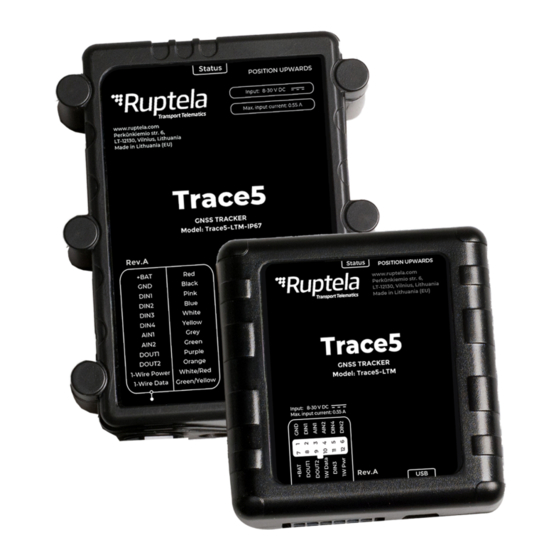
Page 8: Trace5 Product Information
1.1 Trace5 Product Information About Trace5 is a compact GNSS-based telematics device designed to perform a wide range of tasks for fleet management, tracking, safety, and security. A wide choice of models provides connectivity options for every region. The device is available in the following variations: ·... - Page 9 Package content depends on the order and may not contain all of the items listed above. By default, no SIM card is provided in the package. SIM cards can be obtained from your local phone operator. Certifications Trace5 devices have passed quality tests and comply with the following certifications:...
- Page 10 Certification of Economic Commission for Europe is the European E-Mark conformity mark issued by the transport sector, indicating that the product complies with relevant laws and regulations or directives. CE is a certification mark that ensures conformity with health, safety and environmental protection standards for products sold within CE/RED European Economic Area (EEA).
- Page 11 Patents Trace5 is compliant with numerous patents both in the United States and Canada. A full list can be found here.
-
Page 12: Trace5 Technical Information
Digital input 4 AIN1 Grey Analog input 1 AIN2* Green Analog input 2 DOUT1 Purple Digital output 1 DOUT2 Orange Digital output 2 1W Pwr* White/Red 1-Wire Power 1W Data* Green/Yellow 1-Wire Data * – Not available with pre-revision Trace5-LTM devices. Physical Characteristics... - Page 13 Power Consumption @ 12 V DC Operating Idle mode (battery fully charged): 33 mA* (internal battery fully Active mode (peak): ~230 mA charged) Sleep mode (lowest): 5 mA** * – configuration dependent value ** – for pre-revision Trace5-LTM Connectivity Cellular Trace5-2G:...
- Page 14 Reacquisition sensitivity: -152 to -160 dBm Cold start duration: < 30 s Aided start: As low as 3 s * – available upon request ** – will be available with firmware update for Trace5-2G, Trace5-LTE and Trace5-LTM (Rev.A). Interfaces Power Supply Pins...
- Page 15 To monitor the values of various peripherals Parameters Voltage range: 0 – 30 V DC Resolution: 12 bit Applications Various sensors * – Not available in pre-revision Trace5-LTM. Digital Inputs Pins DIN1, DIN2*, DIN3*, DIN4* Purpose To monitor the values of various peripherals Parameters Voltage range: 0 –...
-
Page 16: Trace5 Device Preparation
1.3 Trace5 Device Preparation For the device to work, you first need to insert a SIM card. To do so, open the device housing and perform the actions described below. Opening the Device Use a flat head screwdriver to open the plastic housing. Insert the screwdriver between the top and bottom parts of the housing and lift the top part up as shown in the image below. - Page 17 Use a non-prepaid SIM card to ensure that the balance does not suddenly run out and cause connectivity issues. Closing the Device To close the device, you first need to reinsert the PCB if it was taken out of the housing and attach it to the holding pins.
- Page 18 Cable Connection 12 Pin Cable Connection Connect the wiring harness to the 12 Pin Micro-Fit port on the device as shown in the image below. The harness can be connected in only one way. USB Cable Connection Connect the USB cable to the mini USB port as shown in the image below. The cable can be connected in only one way.
- Page 19 SIM Card Size Comparison When inserting a SIM card into the device, make sure it is inserted correctly as shown on the device and is the correct size. Refer to the image below:...
-
Page 20: Trace5 Device Configuration
1.4 Trace5 Device Configuration Device Center The Device Center application is used to configure the device. The Device Center allows you to do the following: · Make a new configuration file · Edit an existing configuration file · Send a configuration file to your device ·... - Page 21 Starting the Configuration After launching the Device Center, click Configure device in the main menu. Install the device drivers if prompted. You will be directed to the configuration type selection menu. Click Connect device.
- Page 22 Select your device in the device selection menu by clicking on it.
- Page 23 Configuration Menu After device selection, you will be directed to the main configuration menu. This menu has the following elements: 1. An Advanced mode button – opens the advanced configurator 2. Device info – displays information about the connected device 3. An information icon – opens the Device Center user manual 4.
- Page 24 You can upload the same configuration file to multiple devices, making it easy to receive identical data from all your vehicles. File Extension Configuration file extension for Trace5 devices:...
- Page 25 Trace5-LTM (pre-revision): .fa5c Trace5 NA: .fb5c Trace5 (all other versions): .fd5c Configuration files can easily be recognized by their own icon: Loading a Configuration from a File Click Load from file in the button bar. Locate your configuration file and click Open. ...
- Page 26 Click Save to device in the button bar. The configuration will be saved to the connected device. Saving a configuration to a device will overwrite the existing configuration in the device without any confirmation. Essential Settings Only the settings that are essential to use the device are described in this document. For a detailed description of all the additional functionalities, please refer to the Device Center and advanced configuration user manuals.
- Page 27 Backup Server You can use a second server as a backup, in case the main server is unreachable. If the main server is reachable, no data is sent to the backup server. Both servers use the same protocol. The IP address of the backup server. You may enter a numerical address IP/Domain name or a domain name.
- Page 28 The APN username. This parameter is optional. Password The APN password. This parameter is optional. The Trace5-LTE-EMEA and Trace5-LTE-LA devices will not send data if the APN username and/or password are configured due to a known modem issue. Device Management Platform Settings Set, how the device will connect to the device management platform to receive remote firmware and/or configuration updates.
- Page 29 Default value: On Connection frequency Set how often the device will connect to the device management platform. Possible values: · Every 5 minutes · Twice a day Custom · – allows setting the following: Connection frequency (s) –...
- Page 30 Custom Default value: Remote blocking Allows the engine to be blocked remotely via your fleet management platform. It uses a constant connection to the server and increases data consumption by up to 500 kB per month. Default value: Off Decide which detection logic to use and whether to use a delay for state changes. Which logical operator will be used for the engine detection conditions.
- Page 31 Then, decide which conditions you wish to use for engine state detection. If ticked, the condition is true when the configured DIN detects a constant DIN1/DIN2/DIN3/DIN4 input voltage. Default value: DIN4 enabled, other inputs disabled Movement sensor If ticked, the condition is true after detecting movement. Default value: Enabled CAN ignition If ticked, the condition is true if the engine on state is provided by CAN...
- Page 32 GPS speed > If ticked, the condition is true if the speed value obtained from GPS is greater than the entered value. Default value: Disabled CAN speed > If ticked, the condition is true if the speed value obtained from CAN data is greater than the entered value.
- Page 33 · Custom -– configure parameters, to define how often the data should be updated: Ignition off (s) – set how often the location should be 3600 updated when the ignition is off. Default value: s Distance travelled (m) – set how far the vehicle should travel to update the location.
- Page 34 Advanced Configuration The Device Center allows you to configure the main functionalities of your device. If you wish to have additional control over what data is received or to configure more advanced functionalities, you can switch to the advanced configurator by clicking Advanced mode in the top bar at any time. A detailed description of the advanced configurator is available in the advanced configurator user manual.
- Page 35 Manually by sending a firmware file to the device · Over-the-air using your fleet management software The device will not send any data during firmware updates. File Extension Firmware file extension for Trace5 devices: Trace5-LTM (pre-revision): .efwa5 Trace5 NA: .efwb5 Trace5 (all other versions): .efwd5 Updating Firmware Automatically If the Device Center is newer than the detected device firmware, it will suggest updating the firmware.
- Page 36 Updating Firmware Manually This feature requires the use of the Advanced Configurator. Updating Firmware using .efw* Extension Files To update the firmware with the .efw* extension file, click Connect and Send FW in the main configurator menu. Locate your firmware file and click Open. The firmware update process will start. Updating Firmware using .fwp Pack To update the firmware with the .fwp pack, click Connect and Send FW in the main configurator menu.
-
Page 37: Trace5 Installation In Vehicle
1.5 Trace5 Installation in Vehicle Installation Using OBDII Harness Installation Method To install the device, you need to connect it to a power supply and an ignition source. They may be found in the following locations: · The OBD diagnostic port ·... - Page 38 Correct Incorrect Incorrect device installation may result in reduced tracking accuracy. Wiring Diagram Power input: 8-30 V DC. It is mandatory to use an external automotive 1 A fuse. Installation Assistant...
- Page 39 You can test your device during installation using the installation assistant tool in the Device Center. The installation assistant checks the status of the main modules and interfaces in real-time, allowing you to monitor the quality of the installation and quickly solve any issues. If the Overall status in the overview bar is green, the device is functioning properly, and the installation was successful.
- Page 40 The mobile signal level. If lvl is lower than 10, the signal is weak, and it is likely that there is no connection to the network. The internet status. Possible values: GPRS · 0 – no internet connection · 1 – the device is connected to the internet In the previous example, the GPRS value is 0.
- Page 41 sat. The number of visible satellites. At least 4 satellites must be visible to get an accurate GNSS signal. hdop The current HDOP (signal accuracy) level. If the HDOP level is above 3.5, the GNSS signal is inaccurate. The current GNSS state. Possible values: state 1 –...
-
Page 42: Trace5 Using Trusttrack
TrustTrack can be accessed via the web or using an app. Use the same server domain (typically track2.ruptela.com) for both web and app. Your login credentials are sent to you by e-mail. If you have not received them, contact your sales manager. - Page 43 Once downloaded, launch the app. Enter the server domain. You will only need to do this once. Tap Continue. If you entered the server domain incorrectly or wish to change it, clear the app cache in your phone settings. The app will ask you for the server domain upon the next launch. Verifying Vehicle Status After logging in, click the Fleet status button in the left menu panel.
Need help?
Do you have a question about the Trace5 and is the answer not in the manual?
Questions and answers