Table of Contents
Advertisement
Quick Links
Advertisement
Table of Contents

Subscribe to Our Youtube Channel
Summary of Contents for FUTABA BR-4000
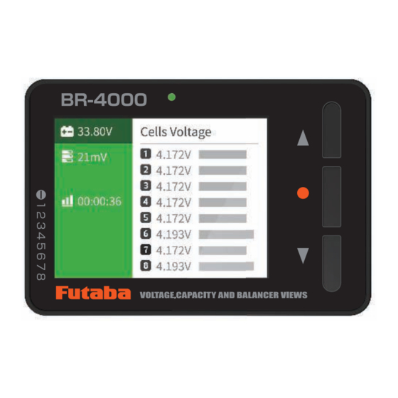
- Page 1 1M23Z09302 Instruction Manual...
-
Page 2: Table Of Contents
Thank you for purchasing the BR-4000. Table Of Contents Warnings and safety notes ………………………………………………… 3 ………………………………………………………………… 4 Nomenclature ……………………………………………………………… 5 Balance port ………………………………………………………………… 5 System function screen …………………………………………………… 6 Measurement display ……………………………………………………… 8 <Battery connection> ……………………………………………………… 8 <BEC power supply connection> ………………………………………… 9 Cell balance …………………………………………………………………... -
Page 3: Warnings And Safety Notes
Warnings and safety notes Securely use this product. Please observe the following safety precautions at all times. Explanation Of Symbols Please observe the following precautions to ensure the safe use of this product. Meaning of Special Markings: The parts indicated by the following marks in this manual require special attention from a safety standpoint. - Page 4 <Battery Pack Care> For safety and to extract maximum performance from the battery pack used, observe the following points: • Discharge and store the battery pack following the battery instruction manual. <Battery Recycling> taking it to a battery recycling center.
-
Page 5: Nomenclature
Nomenclature Balance port This product is suitable for the lithium battery, which has the XH 2.54 balance port, connect the Voltage from XT60i must be more than 5V. -
Page 6: System Function Screen
System function screen display the following system function screen. ・・・ ・・・ How to set system functions * The following is an explanation using the "Language" setting as an example. ・・・ ・・・ to use, press the Menu 日本語 繁體中文 *List 機能 言語... - Page 7 Function menu ・・・ ・・・ Function Settings 日本語 Lanbage 中国語 簡体 中国語 繁体 Backlight Power Save Mode Volume System Information Receiver Tester Alarm Tone Battery Type Low Voltage Alarm USB Charge Cells Balance Back...
-
Page 8: Measurement Display
Measurement display <Battery connection> • When a battery is connected to the XT60i port each cell, you need to connect the balance connector of the battery to the balance port. * XT60i port input voltage 22.93V -.---V -.---V -.---V -.---V -.---V -.---V -.---V... -
Page 9: Bec Power Supply Connection
BEC power supply to -.---V the XT60i port. * The XT60i adapter is not available from Futaba. Cell balance <Start of cell balance> ] twice to start cell balancing. Alternatively, select "Cell Balance" from the "Function" menu, check the "Start" display, and press the menu button [ ] once. -
Page 10: End Of Cell Balance
When the "Power Save Mode" function is on, if no operation is detected during * LED flashes green when operation, the display will turn off, and the display is off the LED will start blinking green to signal that balancing is in operation. [ ] once to display the system once to start cell balancing. -
Page 11: Usb Charge
USB Charge that supports USB charging from the USB charging port. 23.01V -.---V -.---V -.---V -.---V -.---V -.---V -.---V -.---V <Start of USB charging> Connect the battery to the XT60i connector, connect the battery to the USB charging port with the charging cord, and device or battery press the menu button [ ] twice to start USB charging. -
Page 12: Stop Usb Charging
USB connection device (battery) information: XT60i port input alarm voltage: * When the balance port is connected Set to the single cell voltage set in "Low voltage alarm" in the system function menu. When the "Power Saving Mode" is on, the display turns off after 2 minutes of inactivity, and the LED * LED flashes purple when the display is off... -
Page 13: Receiver Signal Testing
Receiver signal testing signal. ・・・ ・・・ Connect to the receiver <PWM> You can check the RC control signal PWM of the system. The servo receiver output signal is connected ・・・ ・・・ <S.BUS> 4000 displays up to 18 channels of servo control data, allowing you to check the signal position during F/S operation. - Page 14 https://www.rc.futaba.co.jp...
Need help?
Do you have a question about the BR-4000 and is the answer not in the manual?
Questions and answers