
Related Manuals for Wheatstone Corporation GPC-3 Studio turret

Summary of Contents for Wheatstone Corporation GPC-3 Studio turret
- Page 1 S Y S T E M G P C - 3 G P C - 3 S Y S T E M S T U D I O T U R R E T ECHNICAL ANUAL Wheatstone Corporation Jan 2006...
- Page 2 GPC-3 Studio Turret Technical Manual GPC-3 Studio Turret Technical Manual GPC-3 Studio Turret Technical Manual GPC-3 Studio Turret Technical Manual GPC-3 Studio Turret Technical Manual ©2006 Wheatstone Corporation 600 Industrial Drive New Bern, North Carolina 28562 tel 252-638-7000 / fax 252-637-1285...
-
Page 3: Table Of Contents
G P C - 3 C O N T E N T S GPC-3 System Table of Contents Chapter 1 – GPC-3 Hardware General Information ..............1-2 GP-3 Headphone Panel ..............1-3 Replacement Parts ....................1-3 GP-3 Pinouts ......................1-4 GP-3 Schematic ......................1-5 GP-3 Load Sheet ...................... - Page 4 G P C - 3 C O N T E N T S Chapter 2 – GP-8P/GP-16P Software Overview ..................2-2 Installation ..................2-2 Setup ....................2-2 Initial Tests ..................2-3 Programming the Panel - an Example ......... 2-4 Programming the Panel - Diving Deeper ........2-6 Startup Code ......................
- Page 5 G P C - 3 C O N T E N T S 5 LIO Example Using Device Properties ..............14 5.1 Configure the Source Signal in XPoint ............14 5.2 Configure the GP-16P LIOs ................15 5.3 Create the Mic Control Script Using Script Wizard ......... 17 5.4 Reviewing the Script Wizard Code ..............
- Page 6 G P C - 3 H A R D W A R E GPC-3 Hardware Chapter Contents General Information ..............1-2 GP-3 Headphone Panel.............. 1-3 Replacement Parts ....................1-3 GP-3 Pinouts ......................1-4 GP-3 Schematic...................... 1-5 GP-3 Load Sheet ....................1-6 GP-4S 4 Switch Mic Control Panel ...........
-
Page 7: General Information
G E N E R A L I N F O R M A T I O N G P C - 3 H A R D W A R E GPC-3 Hardware General Information The GPC-3 system (W# 008710) is comprised of a desk turret (W# 008700) having some combination of the available panels installed. -
Page 8: Headphone Panel
G E N E R A L I N F O R M A T I O N G P C - 3 H A R D W A R E GP-3 Headphone Panel (W# 008705) The GP-3 panel is comprised of a switch, a Low Z level pot, and a headphone jack. All user wiring to the GP-3 panel takes place at the 12-position plug terminal and the RJ-45 connector mounted on the GP-3PCB. - Page 9 G P C - 3 H A R D W A R E Plug Terminal HEADPHONE LT HEADPHONE SH HEADPHONE RT SWITCH N.O. SWITCH COM SWITCH LED + SWITCH LED - RJ-45 Connector HEADPHONE LT HEADPHONE RT SWITCH N.O. HEADPHONE SH SWITCH LED - SWITCH COM SWITCH LED +...
-
Page 10: Schematic
SW_C LED_A LED_C HDPN_LT SW_NO SW_C HDPN_RT LED_C LED_A "ON" SW HDPN_SH CONTRACT NO. GP-3 - Wheatstone Corporation - APPROVALS DATE DRAWN 600 Industrial Drive 6-27-05 New Bern, NC 28562 CHECKED SIZE FSCM NO. DWG. NO. 00S0041 ISSUED W# 700841... -
Page 11: Load Sheet
G P C - 3 H A R D W A R E T op Bottom GP-3 Headphone Panel Load Sheet page 1 - 6 GPC-3 / Jan 2006 GPC-3 / Sep 2006... -
Page 12: Gp-4S 4 Switch Mic Control Panel
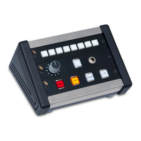
G E N E R A L I N F O R M A T I O N G P C - 3 H A R D W A R E GP-4S 4 Switch Mic Control Panel (W# 008706) The GP-4S panel has “ON,” “OFF,” “COUGH,” and “TB” (talkback) switches for use as a microphone input remote control. - Page 13 G P C - 3 H A R D W A R E Wire these connections to the console mic input channel or Wheatstone Bridge logic card port. Plug Terminal COUGH TB TO CR TALLY OFF TALLY ON REMOTE OFF REMOTE ON GROUND GROUND...
- Page 14 MC+5V "COUGH" SW MC+5V R1 220 "ON" SW "TB" SW MC+5V R2 220 "OFF" SW CONTRACT NO. GP-4S - Wheatstone Corporation - APPROVALS DATE DRAWN 600 Industrial Drive 10-13-05 New Bern, NC 28562 CHECKED SIZE FSCM NO. DWG. NO. 80S0040...
- Page 15 G P C - 3 H A R D W A R E T op Bottom GP-4S 4 Switch Mic Control Panel Load Sheet page 1 - 10 GPC-3 / Jan 2006 GPC-3 / Sep 2006...
-
Page 16: Gp-4W 4 Switch Control Panel
G E N E R A L I N F O R M A T I O N G P C - 3 H A R D W A R E GP-4W 4 Switch Control Panel (W# 008707) The GP-4W panel has four general purpose illuminated switches. All user wiring to the GP-4W panel takes place at the 12-position plug terminal or the RJ-45 connector mounted on the GP-4PCB. - Page 17 G P C - 3 H A R D W A R E Plug Terminal SWITCH 3 SWITCH 4 TALLY 2 TALLY 1 SWITCH 2 SWITCH 1 GROUND GROUND +5V DIGITAL +5V DIGITAL TALLY 3 TALLY 4 RJ-45 Connector GROUND SWITCH 3 SWITCH 4 TALLY 2...
- Page 18 AVAILABLE FOR TALLY3 AND TALLY4 ON THIS CONNECTOR. MC+5V MC+5V MC+5V MC+5V MC+5V MC+5V MC+5V CONTRACT NO. GP-4W - Wheatstone Corporation - APPROVALS DATE DRAWN 600 Industrial Drive 10-13-05 New Bern, NC 28562 CHECKED SIZE FSCM NO. DWG. NO. 80S0040...
- Page 19 G P C - 3 H A R D W A R E T op Bottom GP-4W 4 Switch Control Panel Load Sheet page 1 - 14 GPC-3 / Jan 2006 GPC-3 / Sep 2006...
-
Page 20: Gp-8P 8 Switch Programmable Switch Panel
G E N E R A L I N F O R M A T I O N G P C - 3 H A R D W A R E GP-8P 8 Switch Programmable Switch Panel (W# 008708) The GP-8P panel has eight switches that can be programmed for a variety of functions by using the Ethernet-enabled GUI software (described in Chapter 2). -
Page 21: Gp-8P Pinouts
G E N E R A L I N F O R M A T I O N G P C - 3 H A R D W A R E GP-8P Pinouts RJ-45 Ethernet Connector TXD + TXD - RXD + RXD - Plug the supplied AC adapter into the AC... - Page 22 1.00K 1.00K 1.00K 1.00K R8 39 LED_Y_2 4148 SW_Y_4 LED_Y_3 R9 39 GP-8 CONTRACT NO. 0.1uF - Wheatstone Corporation - APPROVALS DATE 600 Industrial Drive DRAWN 12-5-05 New Bern, NC 28562 CHECKED SIZE FSCM NO. DWG. NO. 80S0038 ISSUED W# 700838...
- Page 23 G P C - 3 H A R D W A R E GP-8P 8 Programmable Switch Panel Load Sheet page 1 - 18 GPC-3 / Jan 2006 GPC-3 / Sep 2006...
- Page 24 +3.3V RJ-45 CONN ETH_TX- RJ_P2 RJ_P8 R66 47 LED_X_0 C87 0.1uF ETHERNET RJ-45 CONNECTOR R63 68 R70 47 R69 47 RJ_P7 DSPL_CLK ETH_TX+ RJ_P1 RJ_P8 LED_X_1 RJ_P7 DSPL_RS DSPL_DIN 0.1uF C92 0.01uF AGND RJ_P6 SW_X_5 SW_X_4 RXD- 0.1uF 0.1uF RJ_P5 SW_X_3 SW_X_2 ETH_RX-...
- Page 25 +3.3V 1.00K +3.3V CPU_PLLHV IN OUT 1.00K +3.3V EMI_FILTER 22uF 0.1uF HP_EN 1.00K FPGA_PGRM PROGRAM_B 1.00K +3.3V +2.5V R56 4.99K FPGA_CCLK HD4/GP[0] CCLK FPGA_DONE HD2/AFSX1 DONE R9 1.00K R61 100 HD3/AMUTE1 ____ FPGA_TMS HAS/ACLKX1 R64 1.00K FPGA_TDI HD1/AXR1[7] HSWAP_EN _____ FPGA_TDO HDS1/AXR1[6] _____...
- Page 26 2.00K 6.19K C10 0.01uF OUT5 DCin POLYSW 1.0A 7 LM2673 1SMB5919 1SMB5919 1SMB5919 MBRD835 330uF 22uF 22uF 47uF 47uF 1500uF 5.6V 5.6V 5.6V 47uF 0.22uF +3.3V OUT IN OUT +3.3V +3.3V LT1117 4.7uF 4.7uF 3.3V 47uF +2.5V OUT IN OUT +2.5V +2.5V LT1117...
-
Page 27: Gpc-1 Load Sheet
G E N E R A L I N F O R M A T I O N G P C - 3 H A R D W A R E Bottom GPC-1 Controller Load Sheet page 1 - 22 GPC-3 / Jan 2006 GPC-3 / Apr 2012... -
Page 28: Gp-16P 16 Switch Programmable Switch Panel
G E N E R A L I N F O R M A T I O N G P C - 3 H A R D W A R E GP-16P 16 Switch Programmable Switch Panel (W# 008709) The GP-16P panel has sixteen switches that can be programmed for a variety of functions by using the Ethernet-enabled GUI software (described in Chapter 2). -
Page 29: Gp-16P Pinouts
G E N E R A L I N F O R M A T I O N G P C - 3 H A R D W A R E GP-16P Pinouts RJ-45 Ethernet Connector TXD + TXD - RXD + RXD - Plug the supplied AC adapter into the AC... - Page 30 SW_Y_3 SW_Y_3 LED_Y_2 LED_Y_6 SW16 4148 4148 SW_Y_4 SW_Y_4 LED_Y_3 LED_Y_7 0.1uF GP-16 CONTRACT NO. - Wheatstone Corporation - APPROVALS DATE DRAWN 8-4-05 600 Industrial Drive New Bern, NC 28562 CHECKED ISSUED SIZE FSCM NO. DWG. NO. 80S0039 W# 700839...
- Page 31 G P C - 3 H A R D W A R E GP-16P 16 Programmable Switches Load Sheet page 1 - 26 GPC-3 / Jan 2006...
-
Page 32: Gpc-3 Chassis Full Size Template
3.708 5.700 GPC-3 Chassis Full Size Template page 1 - 27 GPC-3 / Jan 2006... -
Page 33: Gpc-3 System Parts List
G P C - 3 H A R D W A R E GPC-3 SYSTEM PARTS LIST PART NAME 008700 GPC DESK TURRET GP-U1 UNDER COUNTER MOUNT ASSY 008701 GP-3 HEADPHONE PANEL ASSY 008705 008706 GP-4S SWITCH PANEL ASSY 008707 GP-4W SWITCH PANEL ASSY 008708 GP-8P SWITCH PANEL ASSY... - Page 34 G P - 8 P / G P - 1 6 P S O F T W A R E GP-8P/GP-16P Software Chapter Contents Overview ..................2-2 Installation ..................2-2 Setup ....................2-2 Initial Tests ..................2-3 Programming the Panel - an Example ......... 2-4 Programming the Panel - Diving Deeper ........
-
Page 35: Overview
G P - 8 P / G P - 1 6 P S O F T W A R E GP-8P/GP-16P Software Overview The GP-8P (eight button) and GP-16P (sixteen button) Programmable Button Panels are designed to integrate with the Wheatstone Bridge Router System and provide a variety of general purpose switching functions. -
Page 36: Initial Tests
G P - 8 P / G P - 1 6 P S O F T W A R E Let’s break this down and see what it’s telling us. GP-16P Configu- ration Tool tells us that the application is used to configure the GP-16P panel. -
Page 37: Programming The Panel - An Example
G P - 8 P / G P - 1 6 P S O F T W A R E Programming the Panel – an Example In order to do any useful work you’ll need to get past the canned scripts and write one of your own. - Page 38 G P - 8 P / G P - 1 6 P S O F T W A R E What does it mean? First, there is an action involved – someone is going to press button 1 on the panel (as signified by BTN_1_PRESS), and when they do, we want to know it.
-
Page 39: Programming The Panel - Diving Deeper
G P - 8 P / G P - 1 6 P S O F T W A R E Programming the Panel - Diving Deeper The panel can also be used to interact directly with the system’s Logic I/O cards. The help file has an excellent example that shows how to emulate a mic channel control panel. - Page 40 G P - 8 P / G P - 1 6 P S O F T W A R E at destination 1031. Press the button (it lights) and the fader source changes from the mic on 32 to the mic on 33; release the button (it goes out) and the fader source changes back to the mic on 32.
-
Page 41: Startup Code
G P - 8 P / G P - 1 6 P S O F T W A R E Startup Code It is often useful to have some code execute when a script starts. When using the Script Wizard, there may be some startup code generated for your script automatically in the STARTUP action. -
Page 42: Lio Settings
G P - 8 P / G P - 1 6 P S O F T W A R E LIO Settings We use the LIO settings to map a button or its LED to a logic port in the system. These logic ports may be real (as are the one that we deal with in this section) or virtual (as are the ones used in the example in the help file). -
Page 43: The Helpfile Example
G P - 8 P / G P - 1 6 P S O F T W A R E The Helpfile Example As promised above, the example from the helpfile is duplicated here. LIO Configuration Example Setting up the LIOs properly in your system can be a daunting task. This example is here to show how you could configure your GP-16P button panel to work with a microphone source signal and provide some common microphone type control. -
Page 44: Configure The Gp-16P Lios
G P - 8 P / G P - 1 6 P S O F T W A R E Things to take note of in this diagram are the signal number and the LIOs for each logic function. The signal number and the LIO number will come into play when we configure the logic I/O for the GP-16P. - Page 45 G P - 8 P / G P - 1 6 P S O F T W A R E The Script Wizard assumes a one to one correlation between the LIO number in the GP-16P device properties and the auto generated action which the Script Wizard will generate.
-
Page 46: Create A Script Using The Script Wizard
G P - 8 P / G P - 1 6 P S O F T W A R E Create a Script Using the Script Wizard Now we want to use the script Wizard to generate a script for the GP-16P. Configure the first and second buttons to be Momentary LIO functions with external LED drive. - Page 47 G P - 8 P / G P - 1 6 P S O F T W A R E The auto-generated script code for the first two buttons will assert the input LIO while the button is pressed and de-assert the input LIO when the button is released.
- Page 48 G P - 8 P / G P - 1 6 P S O F T W A R E page 2 – 15 GPC-3 / Jan 2006...
- Page 49 G P - 8 P / G P - 1 6 P S O F T W A R E Note: In this example we have seen how the Script Wizard associates a button with the corresponding LIO from the LIO definitions in the device properties dialog box.
-
Page 50: What's Next
G P - 8 P / G P - 1 6 P S O F T W A R E What’s Next? Read through the help file, try a few examples from there, then go ahead and write the scripts you need. You can make life easier by copying code from the help file and pasting it in the Script Editor. -
Page 51: Appendix
A P P E N D I X Appendix GP-16P Configuration Tool Programming Guide page Appendix – 1 GPC-3 / Jan 2008... -
Page 52: Gp-16P Configuration Tool Programming Guide
Wheatstone Corporation Technical Documentation GP-16P Configuration Tool Programming Guide • Programming Button Functions with the Script Wizard • Creating Custom Scripts with the Script Editor 600 Industrial Drive New Bern, NC 28562 252.638.7000 www.wheatstone.com Revision 1.1 – January 2008 Paul Picard... -
Page 53: Table Of Contents
Table of Contents 1 Introduction 1.1 GP-xx Hardware Compatibility....................3 2 What You Need to Get Started 2.1 GP-16P Configuration Tool Software ..................4 2.2 Physical Network Connection ....................4 2.3 IP Address Settings ........................4 2.4 XPoint Software ......................... 5 2.5 GP-16P Help File ........................ - Page 54 Table of Contents (continued) 7.10 Scripting Router Control ......................29 7.11 Scripting Surface Control ......................29 7.12 Basic Surface functions ......................29 7.13 Advanced Surface Functions ....................30 7.14 Example surf_talk Commands ....................30 8 GP16P Scripting Language Overview 8.1 Case Sensitivity .......................... 31 8.2 Comments ...........................
-
Page 55: Introduction
Introduction This document will guide you through the process of programming a GP-8 or GP-16 panel using the GP-16P Configuration Tool software. This primer document is aimed at familiarizing you with the software’s fundamentals and quickly getting your GP-xx panel up and running using the point and click Script Wizard. -
Page 56: What You Need To Get Started
What You Need to Get Started Before you get started programming let’s review all of the miscellaneous software and connection issues. 2.1 - GP-16P Configuration Tool Software Make sure you have installed the GP-16P Configuration Tool software that came with your product’s install CD-ROM. -
Page 57: Xpoint Software
2.4 - XPoint Software The GP-xx panels may be programmed to control audio and logic signal cross-points, fire Salvos, activate surface presets, and other functions. The GP-16 Configuration Tool may require you to enter Source and Destination signal ID’s, Salvo indexes, and other numerical data based on ID numbers generated in XPoint. -
Page 58: Using Gp-16P Configuration Tool Software
Using GP-16P Configuration Tool Software OK, now that we have the network connection issues taken care of we can start the GP-16P Configuration Tool software and program the panel to perform some basic functions using the Script Wizard. The general procedure we will follow is listed below. 3.1 - Programming Procedure Summary The steps required to program your GP-xx device are listed below - let’s review them and then perform each in turn. -
Page 59: Create A New Script File
3.4 - Create a New Script File Select the Menu item File->New and the Script Wizard opens automatically, once you have specified a file name for the new script. The Buttons list in the scroll pane on left side of the Wizard is where you select which GP panel button you would like to program. -
Page 60: Script Wizard Button Functions
3.5 - Script Wizard Button Functions The following functions may be mapped in any combination to the GP-xx buttons. Note that in some cases a button may perform actions on both the Press and Release of the switch. The Help file includes details; go to Contents>Script Wizard>Button Properties for more information. -
Page 61: Compile The Script
3.6 - Compile the Script Once you have mapped functions to the buttons you are ready to compile the auto-generated Script Wizard code and download it to the GP-xx panel. To compile, select the Build-> Compile and Download menu choice. If successful you will see the following feedback on the screen. -
Page 62: Reviewing The Script Wizard Code
3.9 - Reviewing the Script Wizard Code You can use the Script Editor to see the auto-generated (AG) code produced by the Script Wizard. To view the code select menu item View->Script Editor… Here is a sample Script and its code descriptions: Wizard code starts here >... -
Page 63: Configuring Device Properties
Configuring Device Properties Some applications may require the GP-xx panel to talk to control surfaces or interact with certain signals that have logic functions mapped to them. For instance you may wish to take a Preset or turn a channel ON and OFF on a surface. You might also wish to use the GP-xx panel at a talent microphone location in a studio. -
Page 64: Lio Configuration
in the Script Wizard. The second IP address from the top corresponds to surface "2", the third from the top is surface "3", etc. Unused surfaces should be left blank. Note: The controls will be disabled if you are not connected to the GP-16P device. If you are disconnected, you are actually looking at the device properties which are stored on your PC's hard drive. -
Page 65: Design Philosophy
associated with a microphone source. In a discrete hardwired system these signals would typically come from a button on the announcer’s desk then be fed into an input logic line on an LIO card in your audio router. Custom scripts for your GP-16P can drive input LIOs using the lio_set() function. -
Page 66: Lio Example Using Device Properties
LIO Example Using Device Properties Before we get on with the following example you should understand that there are two primary ways to approach remote control of a surface channel using the GP-xx panel. You can use a custom script to control a specific fader channel on a surface or you can use the Device Properties to “point”... -
Page 67: Configure The Gp-16P Lios
emulating the hardware we will point the LIO associated with JOE's mic to an LIO card which is not actually populated in the router rack. You must add an LIO card to your "Rack Defs" dialog box, since this is the only way to reserve the "Tier, Rack & Slot" numbers used for routing the logic. - Page 68 Define the first four input LIOs to match the Remote On, Remote Off, Cough and Talkback LIOs for the "JOES MIC" signal. Take note that these are configured as "Input" LIOs in the GP-16P since we are sending this logic into the router matrix.
-
Page 69: Create The Mic Control Script Using Script Wizard
5.3 - Create the Mic Control Script Using Script Wizard Now we want to use the Script Wizard to generate a script for the GP-xx. Configure the first and second buttons to be Momentary LIO functions with External LED drive. Then configure the third and fourth buttons to be Momentary LIO functions with Internal LED drive. -
Page 70: Reviewing The Script Wizard Code
5.4 - Reviewing the Script Wizard Code The following script will be generated. The button 1 & 2 actions simply drive the LIOs and LEDs corresponding to the buttons. A periodic timer drives the button 1 & 2 LEDs with the value read from the LIO corresponding to those buttons. -
Page 71: Beyond The Script Wizard
The auto-generated script code for the third and fourth buttons will assert the input LIO while the button is pressed and de-assert the input LIO when the button is released. The button LED will light to indicate that the button is down. action: BTN_3_PRESS //mapped as COUGH in Device Properties btn_led (3,1) lio_set (3,1) -
Page 72: What Is The Script Editor
What is the Script Editor? The Script Editor is a specialized text editor built into the GP-16P Programming tool. This editor provides a convenient way to write custom scripts and also view Script Wizard code. GP-xx scripts are actually specially formatted text files saved with a “.ss “ file extension. The Script Editor automatically separates the Script Wizard code from your custom code by dividing the file into two panes –... -
Page 73: Third Party Editors
6.2 Third Party Editors Scripts may also be opened, written, and edited in a programming oriented editor but care must be taken to be sure that the file structure, formatting, and script syntax is maintained. Avoid using generic text editors like Notepad or Wordpad for script creation. You will know right away at Compile time if there is a problem If you plan on doing a lot of scripting you might consider using a third party programming editor. -
Page 74: Creating Custom Scripts
Creating Custom Scripts A good way to learn how to write custom scripts is through experimentation - so we will open a custom script and examine the format and syntax of the file. Then feel free to edit button behavior and add features. -
Page 75: Auto-Generated Script Components
7.3 - Auto-generated Script Components Notice that the first section of the custom script has a few lines of auto-generated code. These are minimum startup lines and must not be altered or deleted. //AG_START // All code between the AG_START and AG_END tags is auto // generated and should not be modified. -
Page 76: Example Script Structure
Resulting code with new subroutine and some structure comments added. //AG_START // All code between the AG_START and AG_END tags is auto // generated and should not be modified. // Script Generator GUI V1.1.1 //AG_HOOK TYPE="STARTUP" ACTION="mystartup" variable: AG_scratch // Temporary scratch pad variable for AG actions. action: STARTUP call mystartup () //AG_END... -
Page 77: Example Script -Variables And Constants
Scripts must follow a certain format in order for the compiler to evaluate it correctly. The example script follows this format: • AG Start code – auto-generated code from the wizard and a basic startup action. • This code must be present even if you plan on scripting all of the button functions and generally should not be modified. - Page 78 Comments added to the Constants section help readability. Notice how the Destination and Sources are defined as constants. These signal ID numbers could have been “hard coded” as numbers in the Action section but are easier to modify in the future by listing here. Additional comments could include the Source signal names in XPoint or the constant names could even be the Source signal names –...
-
Page 79: Example Script - Subroutines
7.7 - Example Script – Subroutines The example script uses two subroutines – one to handle the switch presses and one to store the last switch pressed so it’s LED can be turned OFF on a subsequent switch press. Note that a custom startup routine was not included. -
Page 80: Example Script - Actions
7.8 - Example Script – Actions For this example each button is given its own Press action. Release and Over-press actions were not required. By putting the “guts” of the script behavior in Subroutines, the Actions are kept simple and straight forward. Each button press uniquely sets the value of “switch” and “source” and then passes those variables to the “handle_sw_press”... -
Page 81: Custom Scripting Suggestions
7.9 - Custom Scripting Suggestions Before you embark on your scripting expedition take the time to map out the requirements in a spread sheet or note pad. Spending a bit of time in the planning phase can save you some headaches later on and will at least make it easier to stay focused on coding once you start getting deep into it. -
Page 82: Advanced Surface Functions
7.13 - Advanced Surface Functions These functions require just a bit more programming knowledge to implement correctly. The function “surf_talk” is very powerful because it allows you to use all of the surface’s Automation Control Interface (ACI) command set. The automation protocol is ASCII based which makes it easy to incorporate ACI commands using the built in surface functions. -
Page 83: Gp16P Scripting Language Overview
GP16P Scripting Language Overview The following Script Language overview may be found in the GP-16PConfiguration Tool’s Help file. The Overview and Structure sections are included for reference and will give you an idea how a script is built. Please refer to the Help File for specific details on writing Statements, Boolean Expressions, etc. The scripting language used to define virtual machine instructions for the programmable button panel is a very simple language to learn. -
Page 84: Local & Static Local Variables
Variable names can be any unique non-reserved identifier. An identifier can be up to 32 characters long. The first character must be a letter; the following characters may be letters, numbers or the underscore character ("_"). All variables in the scripts are treated as character strings. You can define a variable (ie x), assign a text string to x, perform some string operations on x, then assign a number to x, and perform mathematical operations on x. -
Page 85: Gp16P Scripting Language Structure
GP16P Scripting Language Structure 9.1 - Script Structure The structure of a script file is shown below. Global variable declarations must be done at the start of the file before any actions are defined. There can be any number of actions defined in the script file. -
Page 86: Global Array Declarations
9.4 - Global Array Declarations A global array declaration begins with the keyword "array:" and the array name. After the array name an array dimension must be specified. Arrays may be one or two dimensional. The following example shows the structure of global array declarations array: name [size] array: name [size][size] The following example shows the declaration of two global arrays. -
Page 87: Action Parameters
The following example shows a typical action body. This action is named "BTN_1_PRESS". It has two local variables. The variable "count" is a static variable that will be incremented each time the action is executed. After the count is incremented a message string is built up with the count included and the message is printed to the console (a Telnet window). - Page 88 A Subroutine may return one parameter to the caller. The caller will access the returned parameter through the built-in variable name "$0". This parameter will remain valid until the next subroutine call is made. subroutine: sum_up_1 var sum = $1 # $2 # $3 return sum subroutine: sum_up_2 return ($1 + $2 + $3 + $4)
-
Page 89: Script Debugging
Script Debugging If you have delved into writing your own scripts you will inevitably have to debug them - if only to root out spelling or other minor syntax errors. Programming and debugging go hand in hand. Fortunately there are a couple of very useful tools to aid you in your time of need. -
Page 90: Using "Print" And Telnet To Debug
10.3 - Using “Print” and Telnet to Debug The Print statement may be inserted anywhere into the script code to print messages, variable values, etc. to a Telnet window. This feature is extremely useful for tracking down bugs or displaying script behavior in compiled code running on the GP-xx panel. Here’s how it works. - Page 91 Once you are logged on you need to toggle Script Debugging ON. To toggle Script Debug ON type: sdbg 1 <Enter> To turn it OFF type: sdbg 0 <Enter> Now when you press a button on the GP-xx panel running the Example interlock16.ss script, you will see the Print statements as they are executed.
- Page 92 Appendix A A1 - Example Custom Script File – interlock16.ss To open this file in the GP16PConfiguration Tool do the following: 1-Start the GP-16P Configuration Tool software 2- Click File-New 3- Select interlock16 as the filename and click SAVE. 4- The Script Wizard opens automatically – click CANCEL to close it. 5- Select View >Script Editor 6-Copy and paste everything between the //START HERE and //END HERE lines directly into the bottom window of the Script Editor.
- Page 93 //*********************** // Subroutines //*********************** subroutine: handle_sw_press //This subroutine does most of the work. //It receives switch# and source info from the button //press actions. print ("Subroutine-handle_sw_press") switch = $1 source = $2 btn_led (last_led, OFF) call store_switch (switch) connect (dest_a, source) //dest_a is a fixed destination defined above as a constant btn_led (switch, ON) print ("connecting Source ID "...
- Page 94 action: BTN_4_PRESS switch = 4 source = source4 call handle_sw_press(switch, source) action: BTN_5_PRESS switch = 5 source = source5 call handle_sw_press(switch, source) action: BTN_6_PRESS switch = 6 source = source6 call handle_sw_press(switch, source) action: BTN_7_PRESS switch = 7 source = source7 call handle_sw_press(switch, source) action: BTN_8_PRESS switch = 8...
- Page 95 action: BTN_12_PRESS switch = 12 source = source12 call handle_sw_press(switch, source) action: BTN_13_PRESS switch = 13 source = source13 call handle_sw_press(switch, source) action: BTN_14_PRESS switch = 14 source = source14 call handle_sw_press(switch, source) action: BTN_15_PRESS switch = 15 source = source15 call handle_sw_press(switch, source) action: BTN_16_PRESS switch = 16...
Need help?
Do you have a question about the GPC-3 Studio turret and is the answer not in the manual?
Questions and answers