Advertisement
Quick Links
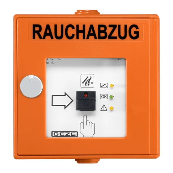
RWA button
FT4 K 24 V DC
136257-01
Symbols and illustrations
Important information and technical notes are emphasised in order
to illustrate the correct operation.
Symbol
Meaning
means "important note";
information on avoiding material damage, understanding
a concept or optimising working processes
means "additional information"
Symbol for an action: Here you have to do something.
X
Observe the sequence if there are several action steps.
X
Safety instructions
à The RWA button may only be used in combination with GEZE
emergency power control units E 260 N (VdS), MBZ 300, THZ
and THZ Comfort.
à Connection is made in accordance with the wiring diagram
for the emergency power control unit.
à Laying and connection of cables may only be carried out by
an approved electrician.
Observe any conditions prescribed by the local fire brigade.
X
Apply the sticker with details of the RWA button number
X
onto the inside of the RWA button on site.
Protect the RWA button from building dirt.
X
Attach the wiring diagram in the RWA button.
X
GB Wiring diagram
Brief description
à The RWA button FT4 K-24V DC is used for manual
triggering in the event of a hazard (fire).
à Surface-mounted housing
à Switching power max. 100 mA at 24 V DC.
à Glass pane replaceable.
à Colours available:
à orange (similar to RAL 2011)
à red (similar to RAL 3000)
à blue (similar to RAL 5009)
à grey (similar to RAL 7035)
à yellow (similar to RAL 1018)
Installation
The RWA button must be installed in a clearly visible
position in the stairwell or corridor and must not be
concealed by an open door leaf.
SMOKE VENT
1
To the emergency power control unit or branch box
4 × 2 × 0.8 with screening
2
Depth 32 mm
3
Distance RWA button – floor
4
To the branch box of the next RWA button FT4 K-24 V
DC 4 × 2 × 0.8 with shield
5
Sticker "Smoke vent"
Initial operation
Connect the RWA button according to the wiring diagrams
X
for the emergency power control unit used.
Test function.
X
Apply the "Smoke vent" sticker in the required language.
X
After the successful function test, open the door of the RWA
X
button and remove the card cover from behind the glass pane.
1.4m 0.2m
Advertisement

Summary of Contents for GEZE FT4 K 24 V DC
- Page 1 To the emergency power control unit or branch box Safety instructions 4 × 2 × 0.8 with screening à The RWA button may only be used in combination with GEZE Depth 32 mm emergency power control units E 260 N (VdS), MBZ 300, THZ Distance RWA button –...
- Page 2 Connection and inner circuit The illustration shows the RWA button with the door opened. OPEN OPEN RWA button Supply terminals Alarm CLOSE/reset switch CLOSE Fire switch/OPEN switch +24 V Last RWA button LED Fire alarm Termination resistors R1/R7 LED Window OPEN *) leave in last RWA button in series LED Operation OK **) remove termination resistors in all series...
- Page 3 Operation The RWA button must be installed in a clearly visible position in the stairwell or corridor and must not be concealed by an open door leaf. In case of fire Break the pane (6) and press the fire switch (7). Displays during operation Pos.
- Page 4 Germany India Russian Federation South Africa GEZE Service GmbH GEZE Industries (Tianjin) Co., Ltd. GEZE Sonderkonstruktionen GmbH Niederlassung Berlin Branch Office Shanghai GEZE India Private Ltd. GEZE GmbH Representative Office DCLSA Distributors (Pty.) Ltd. E-Mail: sk.de@geze.com E-Mail: service-info.de@geze.com E-Mail: chinasales@geze.com.cn E-Mail: office-india@geze.com...
Need help?
Do you have a question about the FT4 K 24 V DC and is the answer not in the manual?
Questions and answers