Advertisement
Quick Links
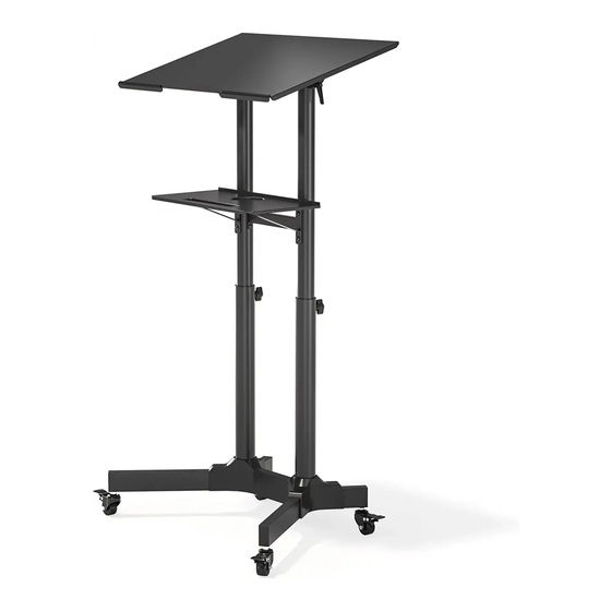
Assembly Instructions for Mobile Workstation
Model: MWS-001BK
Thanks for choosing our product. This stand ideally works as mobile podium,
lectern and laptop workstation. The height of stand can be easily adjusted.
The integrated wheels provide ease of movement.
Advertisement

Summary of Contents for BONTEC MWS-001BK
- Page 1 Assembly Instructions for Mobile Workstation Model: MWS-001BK Thanks for choosing our product. This stand ideally works as mobile podium, lectern and laptop workstation. The height of stand can be easily adjusted. The integrated wheels provide ease of movement.
-
Page 2: Safety Warning
Safety Warning : If you do not understand these directions, or have any doubts about the safety of the installation, please call a quali ed contractor. Check carefully to make sure there are no missing or defective parts. Never use defective parts. Improper installation may cause damage or serious injury. Do not use this product for any purpose that is not explicitly speci ed in this manual. - Page 3 Lever Soft Pad M6x60 Allen Head Bolt M6x10 Allen Head Bolt Q (X2) R (X2) S (X8) T (X12) M4X6 Countersink Bolt M5x6 Grub Screw M6 Washer U (X4) V (X2) W (X2) 13/64 in (5mm) 3/32 in (2.5mm) 5/32 in (4mm) Large Allen Key Wrench Small Allen Key...
- Page 4 Step 2 hole for connecting the Pole Set(G) Note: The short square tube[B] should be on the same side as the screw hole for pole set[G]. Step 3 Note: Adding plastic sleeves to prevent pulling out the inner poles from outer poles.
- Page 5 Step 4 Note: Make sure both of the poles are at the same height Step 5...
- Page 6 Step 6 Note: The Shelf Supports,facing Them To The Long Square Tube...
- Page 7 Step 7 Step 8...
- Page 8 Step 9 Step 10...
- Page 9 Step 11 Step 12...
- Page 10 Step 13 tilt 40° Tilt Adjustment 1. Slightly loosen the both levers [ 2. Tilt the top plate to your desired angle. 3.Re-tighten the both levers [ ] to secure the height in place. Height Adjustment 1. Slightly loosen the both knobs [ 2.
- Page 11 Step 13...
Need help?
Do you have a question about the MWS-001BK and is the answer not in the manual?
Questions and answers
We do not understand how to attach the plastic sleeves to the poles to stop the poles going through - step 3 in the assembly instructions
To attach the plastic sleeves to the poles for the BONTEC MWS-001BK, follow these steps:
1. Identify the Poles: Locate the pole set (G) and the plastic sleeves.
2. Insert the Plastic Sleeves: Slide the plastic sleeves onto the inner poles.
3. Ensure Proper Placement: The plastic sleeves help prevent the inner poles from being pulled out of the outer poles.
4. Continue Assembly: Proceed with the remaining assembly steps after securing the plastic sleeves.
This step ensures stability and proper function of the height-adjustable feature.
This answer is automatically generated