Advertisement
Important
SAVE THESE INSTRUCTIONS— These instructions contain important operating instructions for the CT-M500.
This device connects to a transceiver through a Wireless LAN (WLAN) and expands the transceiver's functions.
For the WLAN setting, the functions that you can operate when connecting to the transceiver, and so on, see the transceiver's manual for details.
The transceiver's manual can be the following internet address: https://www.icomjapan.com/support/
 These instructions are described based on the CT-M500 firmware version 1.00.
Explicit definitions
| WORD | DEFINITION |
 | Personal injury, fire hazard or electric shock may occur. |
 | Equipment damage may occur. |
| NOTE | If disregarded, inconvenience only. No risk of personal injury, fire or electric shock. |
Icom is not responsible for the destruction, damage to, or performance of any Icom or non-Icom equipment, if the malfunction is because of:
- Force majeure, including, but not limited to, fires, earthquakes, storms, floods, lightning, other natural disasters, disturbances, riots, war, or radioactive contamination.
- The use of Icom devices with any equipment that is not manufactured or approved by Icom.
Icom, Icom Inc. and the Icom logo are registered trademarks of Icom Incorporated (Japan) in Japan, the United States, the United Kingdom, Germany, France, Spain, Russia, Australia, New Zealand, and/or other countries. NMEA 2000 is a trademark of the National Maritime Electronics Association, Inc.
All other products or brands are registered trademarks or trademarks of their respective holders.
READ ALL INSTRUCTIONS carefully and completely before using this product.
FCC information
This equipment has been tested and found to comply with the limits for a Class B digital device, pursuant to part 15 of the FCC Rules. These limits are designed to provide reasonable protection against harmful interference in a residential installation. This equipment generates, uses, and can radiate radio frequency energy and, if not installed and used in accordance with the instructions, may cause harmful interference to radio communications. However, there is no guarantee that interference will not occur in a particular installation. If this equipment does cause harmful interference to radio or television reception, which can be determined by turning the equipment off and on, the user is encouraged to try to correct the interference by one or more of the following measures:
- Reorient or relocate the receiving antenna.
- Increase the separation between the equipment and receiver.
- Connect the equipment into an outlet on a circuit different from that to which the receiver is connected.
- Consult the dealer or an experienced radio/TV technician for help.
Changes or modifications to this device, not expressly approved by Icom Inc., could void your authority to operate this device under FCC regulations.
Recommendation
CLEAN THE DEVICE THOROUGHLY WITH FRESH WATER after exposure to saltwater, and dry it before using. Otherwise, the device's keys may become unusable, due to salt crystallization.
NOTE: If the device's waterproof protection appears defective, carefully clean it with a soft, damp (fresh water) cloth, then dry it before operating.
The device may lose its waterproof protection if the case is cracked or broken, or the device has been dropped.
Contact your Icom distributor or your dealer for advice.
About CE and DOC

Hereby, Icom Inc. declares that the versions of CT-M500 which have the "CE" symbol on the product, comply with the essential requirements of the Radio Equipment Directive, 2014/53/EU, and the restriction of the use of certain hazardous substances in electrical and electronic equipment Directive, 2011/65/EU. The full text of the EU declaration of conformity is available at the following internet address: https://www.icomjapan.com/support/
Precautions

NEVER connect the device directly to an AC outlet. This may cause a fire or an electric shock.
NEVER connect the device to a power source of more than 16 V DC such as a 24 V battery. This connection could cause a fire or damage the device.
NEVER reverse the DC power cable polarity. This could cause a fire or damage the equipment.
NEVER cut the DC power cable between the DC power connector and the fuse holder. If an incorrect connection is made after cutting, the device may be damaged.
NEVER operate the device during a lightning storm. It may result in an electric shock, cause a fire or damage the device. Always disconnect the power source and other connectors before a storm.
NEVER place the device where normal operation of the vessel may be hindered, or where it could cause bodily injury.
DO NOT use or leave the device in areas with temperatures below –20°C ~ +60°C (–4ºF ~ +140ºF), or in areas subject to direct sunlight, such as a dashboard.
DO NOT use harsh solvents such as Benzine or alcohol when cleaning. This could damage the equipment surfaces. If the surface becomes dusty or dirty, wipe it clean with a soft, dry cloth.
NEVER place the device in an insecure place to avoid inadvertent use by unauthorized persons.
BE CAREFUL! The device's rear panel may become hot when continuously using for long periods of time.
BE CAREFUL! The device meets IPX7 requirements for waterproof protection*. However, once the device has been dropped, or the waterproof seal is cracked or damaged, waterproof protection cannot be guaranteed because of possible damage to the case or the waterproof seal.
* Except for the DC power connector and AF Out leads.
NOTE:Install the device more than 1 meter from the vessel's magnetic navigation compass.
NOTE:Install the device within approximately 15 meters from the transceiver or an existing access point, and in a place where there are no obstacles between the device and the transceiver.
IC-M510 and CT-M500 RF Safety warning
An internal Wireless LAN module and an antenna are supplied with the IC-M510 and CT-M500.
To comply with FCC/ISED RF Exposure for the installed Wireless LAN unit, the device should be installed and operated with a minimum distance of 20 cm between the device and all persons. No other transmitting antenna is permitted to be located within 20 cm of the device.
Disposal

The crossed-out wheeled-bin symbol on your product, literature, or packaging reminds you that in the European Union, all electrical and electronic products, batteries, and accumulators (rechargeable batteries) must be taken to designated collection locations at the end of their working life. Do not dispose of these products as unsorted municipal waste. Dispose of them according to the laws in your area.
Electromagnetic Interference
When you use a Wireless LAN, pay attention to the following: Wireless LAN products operate in the 2.4 GHz band. The 2.4 GHz band is also used by other devices, such as Bluetooth devices, microwave ovens, RFID systems, amateur radio stations, and so on.
When using this device near such devices, interference may occur, causing a decrease in communication speed, and an unstable connection. In such cases, use this device away from the other devices, or stop using those devices.
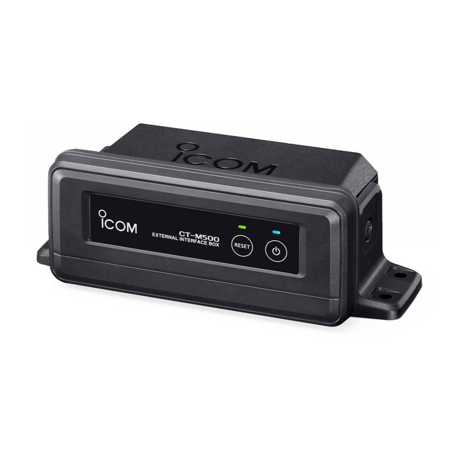
Panel description

- Front panel
- STATUS INDICATOR
Blinks green: Searching the transceiver.
Lights green: Connecting to the transceiver.
Lights red: Entering the WLAN Setup mode and waiting until the transceiver sets the WLAN setting. - POWER INDICATOR
Lights blue when the device is turned ON. - POWER KEY
![]()
Hold down for 1 second to turn the device ON or OFF.
![information]() The device automatically connects to the transceiver.
The device automatically connects to the transceiver.
![information]() If the WLAN setting is not set, the device enters the WLAN Setup mode and waits until the transceiver sets the WLAN setting.
If the WLAN setting is not set, the device enters the WLAN Setup mode and waits until the transceiver sets the WLAN setting. - RESET KEY [RESET]
Hold down [RESET] for 3 seconds when the device is turned ON to reset the WLAN setting.
![information]() The Status indicator blinks red while holding down [RESET].
The Status indicator blinks red while holding down [RESET].
![information]() The device also restarts in the WLAN Setup mode and waits until the transceiver sets the WLAN setting.
The device also restarts in the WLAN Setup mode and waits until the transceiver sets the WLAN setting.

Supplied accessories


- Rear panel
- AF OUT LEADS
Connects to an External Horn Speaker.
Blue: External Horn Speaker (+)
Gray: External Horn Speaker (–)
Black, Orange: NC (Disconnected)
NOTE: The connectors are attached to keep the leads together. Before connecting to a piece of equipment, cut the leads to remove the connector. - DC POWER CONNECTOR
Connects to a 13.8 V DC power source.
(+: Red, –: Black) - NMEA 2000 CONNECTOR
Connects to an NMEA 2000 network. - GROUND TERMINAL
Connects to a vessel ground to prevent electrical shocks and interference from other equipment occurring. Use a PH M3 × 6 screw (user supplied).
![]()
After connecting the DC power cable and AF Out leads, cover the connector and leads with an adhesive tape, as shown below, to prevent water seeping into the connection.


Installing
You can mount the device on a dashboard using the universal mounting bracket supplied with your device.
- KEEP the device at least 1 meter (3.3 ft) away from the vessel's magnetic navigation compass.
- INSTALL the device within approximately 15 meters from the transceiver, and in a place where there are no obstacles between the device and the transceiver.
- Mount the bracket securely to a surface which is more than 10 mm thick and can support more than 5 kg using the 4 supplied screws (5 × 20 mm).
NOTE: When mounting the device on a board, fix the bracket to the board using the user supplied bolts and nuts, as shown below. - Attach the device to the bracket.
Mounting Example

Fuse replacement
One fuse is installed in the supplied DC power cable. If the fuse blows or the device stops functioning, track down the source of the problem, repair it, and replace the damaged fuse with a new one of the proper rating.
Fuse rating: 250 V 5 A

Fuse Coding explanation
Fuse Coding: F 250 V 5 A
Fuse Voltage Rating: 250 Volts
Fuse Current Rating: 5 Amperes
Specifications and options
- Specifications
| General | |
| Operating temperature range | –20°C ~ +60°C, –4ºF ~ +140ºF |
| Power supply requirement | Negative ground: 13.8 V DC nominal (10.8 ~ 15.9 V) |
| Current drain (at 13.8 V) | 3.5 A maximum |
| Dimensions (approximate) ( projections not included) | 156.5 (W) × 67.6 (H) × 82.1 (D) mm, 6.2 (W) × 2.7 (H) × 3.2 (D) in |
| Weight (approximate) | 430 g, 15.2 oz |
| Wireless LAN | |
| Wireless LAN standard | IEEE802.11 b/g/n |
| Authentication and Encryption | WEP (64/128 bit), WPA-PSK (TKIP), WPA2-PSK (AES) |
| Channels | 1 to 13 (2.4 GHz band)
|
| Output power | Less than 10 mW/MHz |
| Hailer | |
| Audio output power | More than 25 W into a 4 Ω load |
| RX Hailer | |
| Audio output power | More than 20 W into a 4 Ω load |
-
Dimensions


- Options
- SP-37 HORN SPEAKER

Documents / Resources
References
Download manual
Here you can download full pdf version of manual, it may contain additional safety instructions, warranty information, FCC rules, etc.
Advertisement

Need help?
Do you have a question about the CT-M500 and is the answer not in the manual?
Questions and answers