Advertisement
Power Supply voltage: 9-12V (DC voltage)
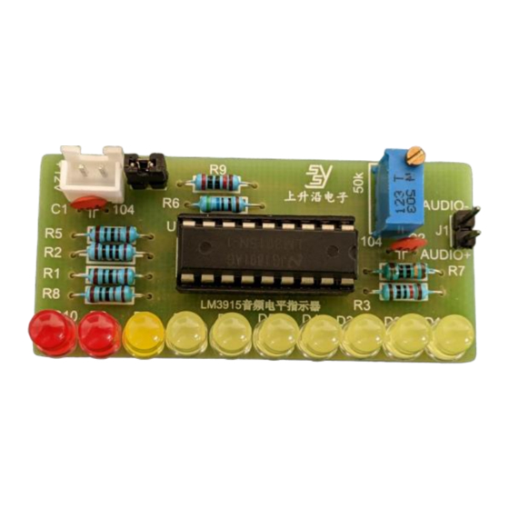
PCB Full Assembly
(Board size: 27*58mm)
_____________________________________________________________________________________
For purchase & enquiries, please contact sales@synacorp.com.my or call 04-5860026
STS-105A: LM3915 AUDIO LEVEL INDICATOR DIY KIT
Schematic Diagram
Component List
R1, R5 & R8=1k
, R2=100
Ω
R3=10kΩ, R4=50kΩ Variable Resistor,
R6=560Ω, R7=10Ω, R9=20kΩ, C1 &
C2=104 Ceramic Capacitor, U1=IC
LM3915, D9 & D10= Red LED, D1-
D8=Yellow LED, J2=XH2.54-2P
Connector, J1 & J3=Male Header 2 Pin,
IC Socket 18 Pin & PCB Board.
Total Item = 26
Ω,
Advertisement
Table of Contents

Related Manuals for SYNACORP STS-105A

Summary of Contents for SYNACORP STS-105A
- Page 1 D8=Yellow LED, J2=XH2.54-2P Connector, J1 & J3=Male Header 2 Pin, IC Socket 18 Pin & PCB Board. PCB Full Assembly Total Item = 26 (Board size: 27*58mm) Schematic Diagram _____________________________________________________________________________________ For purchase & enquiries, please contact sales@synacorp.com.my or call 04-5860026...
- Page 2 Connection Setup 1: Use DIY KIT with Audio Jack Connector that connected to audio input source (phone). one as Audio Connection Setup 2: Use DIY KIT with Microphone Module kit STS-105B as audio source input for Cordless Audio Level Meter Power Supply Audio _____________________________________________________________________________________ For purchase & enquiries, please contact sales@synacorp.com.my or call 04-5860026...
Need help?
Do you have a question about the STS-105A and is the answer not in the manual?
Questions and answers