Advertisement
Overview
Read this guide thoroughly and follow the installation and o peration procedures carefully to prevent any damage to the hub and/or any of the devices it connects to.
This package contains:
- 1 Bidirectional Serial/Parallel C onverter (SXP-320A or SXP-325A)
- 1 AC 9V 200mA Power Adapter
- 1 User Manual


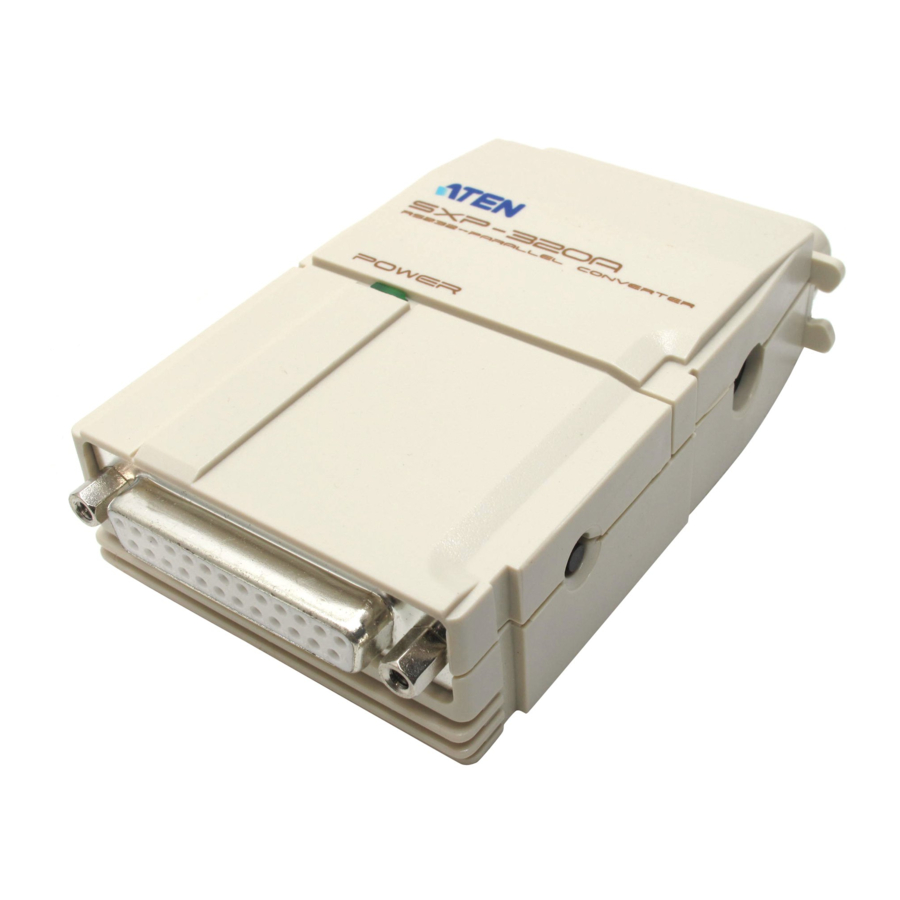
The SXP-320A / SXP-325A are interface converters that allow Centronics and RS-232 devices to communicate with each other (a computer with an RS-232 output to a Centronics printer, for example).
Both units are bidirectional enabling you to convert from serial to parallel or parallel to serial. The primary difference between them is that the SXP-325A is configured with 512 KB of memory allowing it to serve as a printer buffer, whereas the SXP-320A has no memory.
These two way converters provide a DB-25 RS-232C (DCE) compatible connector, and a C-36 Centronics connector. The serial baud rate is from 1200 to 115200 bps. (selectable by DIP Switch). The parallel interface speed for the (nonbuffered) SXP-320A is 11.52 KB/sec; for the (buffered) SXP325A, it is 1.5 MB/sec.
The units support both hardware and software (XON/XOFF) handshaking. Setup is extremely easy. All that is involved is setting the DIP Switch and connecting the cables.
Features
- DIP Switch Sets Data Direction
- Built In Buffer for Efficient Operation (SXP-325A)
- Both Hardware and XON/XOFF Handshaking
- Easy Installation
- Compact Size
Installation
Switch Configuration Overview:
The SXP-320A/325A is configured by setting an eight segment DIP Switch as follows:
| Switch | Purpose |
| 1 2 3 | Baud rate setting |
| 4 | Handshake setting |
| 5 | Data and Stop Bits setting |
| 6 7 | Parity setting |
| 8 | Conversion Direction setting |
An explanation of each DIP Switch setting is given below.
Note:
- When the segment is set in the direction of the arrow, it is ON.
- In each table, the default setting is highlighted
Setting the Switches
Baud Rate:
The baud rate is set with DIP Switch segments 1 - 3, as shown in the table, below
| DIP Switch Segment | Baud Rate (bits per second) | ||
| 1 | 2 | 3 | |
| ON | ON | ON | 1200 |
| ON | ON | OFF | 2400 |
| ON | OFF | ON | 9600 |
| ON | OFF | OFF | 14400 |
| OFF | ON | ON | 19200 |
| OFF | ON | OFF | 38400 |
| OFF | OFF | ON | 57600 |
| OFF | OFF | OFF | 115200 |
Handshake:
| DIP Switch Segment | Handshake |
| 4 | |
| ON | XON/XOFF |
| OFF | Hardware |
Data and Stop Bits:
| DIP Switch Segment | Data Bits | Stop Bits |
| 5 | ||
| ON | 7 | 2 |
| OFF | 8 | 1 |
Parity:
| DIP Switch Segment | Parity | |
| 6 | 7 | |
| ON | Either | Parity Inhibit |
| OFF | ON | Even Parity |
| OFF | OFF | Odd Parity |
Conversion Direction:
| DIP Switch Segment | Conversion Direction |
| 8 | |
| ON | Parallel to Serial |
| OFF | Serial to Parallel |
Cabling
Serial to Parallel:

When performing a Serial to Parallel interface conversion:
- Plug the female end of a 25/9-pin to 25/9-pin male/female serial cable into the PC's serial port
- Plug the male end of the 25-pin to 25-pin male/female serial cable into the SXP-320A/SXP-325A's serial connector
- Plug the female end of a C-36 to C-36 male/female printer cable into the SXP-320A/SXP-325A's printer connector
- Plug the male end of the C-36 to C-36 male/female printer cable into the printer.
Note: If your serial cable is long enough, you can plug the SXP-320A/SXP-325A directly into the printer, without the need for a printer cable. - Plug the Power Adapter into an AC source; plug the Power Adapter cable into the SXP-320A/SXP-325A's power jack.
Parallel to Serial:
When performing a Parallel to Serial interface conversion: 
- Plug the male end of a 25-pin (male) to C-36 (female) printer cable into the PC's parallel port
- Plug the female end of the 25-pin to C-36 male/female printer cable into the SXP-320A/SXP-325A's Centronics connector
- Plug the male end of a 25-pin to 25-pin male/female serial cable into the SXP-320A/SXP-325A's serial connector
- Plug the female end of the 25-pin to 25-pin male/female serial cable into the printer's serial port
- Plug the Power Adapter into an AC source; plug the Power Adapter cable into the SXP-320A/SXP-325A's power jack.
Serial Port Cabling

Parallel Port Cabling 
Operation
When operating the SXP-320A/SXP-325A, please take note of the following:
- Since the SXP-320A/SXP-325A is a DCE device, the serial device it connects to must be configured as a DTE device.
- In DCE mode, the unit uses RTS/DTR (pins 5 and 6) handshaking. When RTS/DTR is at +9V, the computer is allowed to transmit data. When the unit is busy, it sets the RTS/DTR line to -9V, and the computer stops transmitting data. Consequently, if the computer can not identify the RTS/DTR signal, it may result in data loss.
- The unit is powered by the host RS-232C interface. In addition to the TxD line, it is recommended that the host RS-232C interface (MC 1488, SN 75188, or equivalent IC's), also support RTS and DTR lines, which provide a power source above 9V, to ensure normal operation of the unit.
- The unit's baud rate, data length, stop bits and parity settings must be configured to match those of the computer.
- You must reset the parallel printer before printing.
Troubleshooting
| Problem | Cause | Solution |
Power LED does not light | Unit is not receiving power. | Make sure that there is no problem with the AC source, and that the AC adapter is fully operational. |
| Make sure that the adapter is correctly plugged into the AC source and that the cable is fully plugged into the unit's power jack. | ||
No Data Transmission | Cables are not properly plugged in. | Make sure that all cables are properly plugged in and fully seated in their connectors. |
| Cables are not properly wired. | Rewire the cables making sure they are correctly wired | |
| Transmitting or Terminal device has not been set Ready for data transfer. | If powered O ff, turn the device O n. O therwise, reset the Transmitting or Terminal device. | |
| Transmitting or Terminal device is in incorrect DTE mode. | C hange the Transmitting or Terminal device to the correct DTE mode, or user's cross line. | |
Incorrect Data Received | Lines are not properly connected. | Rewire the cable lines to be sure they are properly connected. |
| Incorrect serial transmission DIP Switch settings | Set the DIP Switch segments to their proper settings. |
If the above solutions fail to alleviate the problem, contact your dealer for help.
RS-232C Interface Specification
The RS-232C Interface DCE mode (default) specification is given in the table, below:
| Pin | Name | Function |
| 1 | Ground | Ground |
| 2 | RxD | Receive Data |
| 3 | TxD | Transmit Data |
| 4 | CTS | Clear to Send |
| 5 | RTS | Request to Send |
| 6 | DTR | Data Terminal Ready |
| 7 | Ground | Ground |
| 8 | CD | Pull Up (+9V) |
| 20 | DSR | Data Set Ready |
Centronics Interface Specification
The Centronics Interface Specification is given in the table, below:
| Pin | Name | Function |
| 1 | STB | DATA STROBE |
| 2 | DATA BIT 1 | DATA BUS |
| 3 | DATA BIT 2 | |
| 4 | DATA BIT 3 | |
| 5 | DATA BIT 4 | |
| 6 | DATA BIT 5 | |
| 7 | DATA BIT 6 | |
| 8 | DATA BIT 7 | |
| 9 | DATA BIT 8 | |
| 10 | ACK | DATA RECEIVED ACKNOWLEDGE |
| 11 | BUSY | DEVICE BUSY OR NOT |
| 12 | PAPER EMPTY PULL UP | |
| 13 | SLCT | PULL UP |
| 14 | A-F | PULL UP |
| 15 | N.C. | |
| 16-17 | GROUND | GROUND |
| 18 | N.C. | |
| 19-30 | GROUND | GROUND |
| 31 | INIT | PULL UP |
| 32 | ERR | PULL UP |
| 33 | GROUND | GROUND |
| 34-35 | N.C. | |
| 36 | SL-1 | PULL DOWN |
Centronics Interface Timing Chart 
Specifications
| Power Consumption | AC 9V 150m A (max.) | |
| Cable Distance | Up to 9 m (30') | |
| Connectors | RS-232C | DB-25 female DCE |
| Centronics | C-36 male | |
| Memory Size | 512 KB(SXP-325A Only) | |
| Interface Exchange | In | Serial or Parallel |
| Out | Parallel or Serial | |
| Serial Communications Mode | DCE Only | |
| LEDs | Power (Green) | |
| Microcontroller | ASIC | |
| Function Key | Reset | |
| Buffer Speed | Serial | 1200 - 115200 bps |
| Parallel | 1.5 MB/sec. (max.) | |
| Data Compression | 8.5: 1 (max.) | |
| Temperature | Operating | 5˚ - 40˚ C |
| Storage | -20˚ - 60˚ C | |
| Humidity | 0 - 80% | |
| Housing | Plastic | |
| Weight | 120 g | |
| Dimensions (L x W x H) | 101 x 62 x 25.5 mm | |
Radio & TV Interference

This equipment generates, uses and radiates radio frequency energy and if not installed and used in accordance with the instruction manual may cause interference to radio and television reception. It has been tested and found to comply with the limits for a Class A computing device in accordance with the specifications in Subpart J of Part 15 of the FCC Rules, which are designed to provide reasonable protection against such interference when operated in a commercial environment. Operation of this equipment in a residential area is likely to cause interference, in which case the user at his own expense will be required to take whatever measures may be required to correct the interference.
If this equipment does cause interference to radio or television reception, which can be determined by turning the equipment off and on, the user is encouraged to try to correct the interference by one or more of the following measures:
- Reorient the receiving antenna.
- Relocate the computer with respect to the receiver.
- Move the computer away from the receiver.
- Plug the computer into a different outlet so that the computer and receiver are on different branch circuits.
- Ensure that the mounting screws, attachment connector screws and ground wires are tightly secured.
- Ensure that good quality shielded and grounded cables are used for data communications.
If necessary, the user should consult the dealer or an experienced radio/television technician for additional suggestions.
Limited Warranty
IN NO EVENT SHALL THE DIRECT VENDOR'S LIABILITY FOR DIRECT, INDIRECT, SPECIAL, INCIDENTAL, OR CONSEQUENTIAL DAMAGES RESULTING FROM THE USE OF THE PRODUCT, DISK, OR ITS DOCUMENTATION EXCEED THE PRICE PAID FOR THE PRODUCT.
The direct vendor makes no warranty or representation, expressed, implied, or statutory with respect to the contents or use of this documentation, and especially disclaims its quality, performance, merchantability, or fitness for any particular purpose.
The direct vendor also reserves the right to revise or update the device or documentation without obligation to notify any individual or entity of such revisions, or update. For further inquiries, please contact your direct vendor.
Radio & TV Interference
This equipment has been tested and found to comply with the limits for a Class B digital device, pursuant to Part 15 of the FCC Rules. These limits are designed to provide reasonable protection against harmful interference in a residential installation. This equipment generates, uses and can radiate radio frequency energy and if not installed and used in accordance with the instructions, may cause harmful interference to radio communications. However, there is no guarantee that interference will not occur in a particular installation.
©Copyright 1999 ATEN® International C o., Ltd.
Printed in Taiwan 06/1999
All brand names and trademarks are the registered property of their respective owners.

Documents / ResourcesDownload manual
Here you can download full pdf version of manual, it may contain additional safety instructions, warranty information, FCC rules, etc.
Advertisement
Need help?
Do you have a question about the SXP-320A and is the answer not in the manual?
Questions and answers