Advertisement
Quick Links
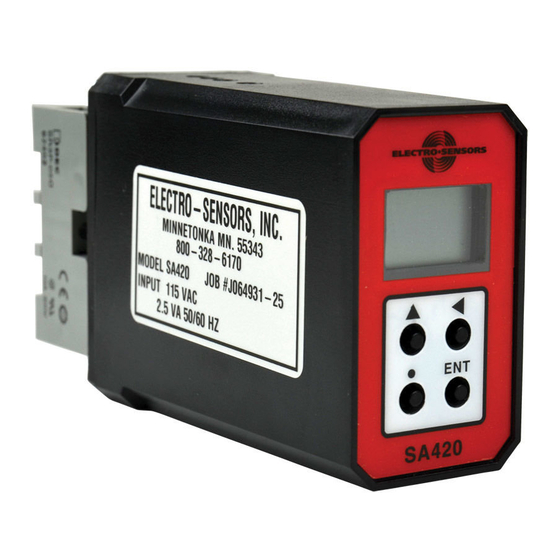
SA420 Signal Conditioner
B
A
OUT%
VAR
RATE
ENT
Figure 1: Standard Sensor with 255 Pulser Disc
SA420
Description:
A
Electro-Sensor's SA420 Signal Conditioner provides an analog signal
directly proportional to the speed of a monitored shaft. The 0-10 VDC
and 4-20 mA outputs can be sent to a chart recorder, digital display, PLC,
A
loop controller, drive speed controller, or other control or monitoring
devices. The wide voltage range and wave shape flexibility of the
SA420's sensor input circuitry allow it to translate signals from Hall-
Effect Sensors, proximity switches, magnetic sensors, and a wide variety
of other pulse generator devices into analog outputs.
Figure 2: Standard Sensor with optional Pulser Wrap
Sensor Installation:
The standard sensor is supplied with a mounting bracket and two jam
nuts. The explosion-proof sensor is supplied with a slotted mounting
B
bracket. Sensors should be installed so the centerline of the magnets
pass in front of the center of the sensor as the disc or wrap rotates. When
using the pulser disc, the center of the magnetized area of the disc,
shown as Dimension B in figures 1 and 3, is 1-3/4 inches from the center
hole of the disc. The gap distance between the sensor and the disc or
wrap, Dimension A In the diagrams, is 1/4-inch ±1/8 inch. To achieve
A
the proper gap distance, adjust the jam nuts holding the standard sensor
in the mounting bracket, or adjust the position of the explosion-proof
sensor using the slots on its mounting bracket.
Figure 3: Explosionproof Sensor with 255 Pulser Disc
Pulser Disc:
The end of the shaft to be monitored must be center drilled to a depth of
1/2-inch with a No. 21 drill and tapped for 10-32UNF. After applying
A
Loctite™ or a similar adhesive on the threads to keep the pulser disc
tight, the pulser disc should be attached, decal side out, with the supplied
10-32UNF machine screw and lock washer.
A
Pulser Wrap (optional):
Pulser Wraps are custom manufactured to fit the shaft they will be
mounted on. When the wrap is shipped, four Allen-head cap screws hold
the two halves of the wrap together. These screws must be removed so
that the wrap is in two halves. Place the halves around the shaft, reinsert
the screws and torque them to 5 foot-pounds max.
Figure 4: Explosionproof Sensor with Pulser Wrap
6111 Blue Circle Drive
Free Catalog and Application Assistance
Minnetonka, MN 55343
1.800.328.6170
Phone: 952.930.0100
Visit Us Online
Fax: 952.930.0130
www.electro-sensors.com
ISO 9001:2015 Certified
990-001700 Revision I
Advertisement

Related Manuals for Electro-Sensors SA420

Summary of Contents for Electro-Sensors SA420
- Page 1 The wide voltage range and wave shape flexibility of the SA420’s sensor input circuitry allow it to translate signals from Hall- Effect Sensors, proximity switches, magnetic sensors, and a wide variety of other pulse generator devices into analog outputs.
- Page 2 SA420 Signal conditioner For version 3 hardware with version 5.xx or later firmware The SA420 now includes the following features: • Quadrature (directional decoding) • Bipolar voltage output (units now include +/- 5 VDC and +/- 10 VDC) • Optional higher NPN input signal trip point (improves operation through IS barrier) •...
-
Page 3: Wiring Connections
Example: A customer has a motor rotating at 1200 RPM and wants the RATE SA420 to output 20mA at 1250 RPM using a Hall Effect sensor and an ESI 255 disc. Since the Hall Effect sensors turns on with a south field and off with a north field, the 255 disc’s 16 alternating magnets (8 north and 8 south... - Page 4 Free Catalog and Application Assistance 1.800.328.6170 Website: www.electro-sensors.com 990-001700 Revision I...
- Page 5 [PR (01)] with their upper setpoint [PR (00)]. **Reverse numbers are represented by a flashing “rate” icon and cannot be programmed until PR (07) is set for quadrature operation. Free Catalog and Application Assistance 1.800.328.6170 Website: www.electro-sensors.com 990-001700 Revision I...
- Page 6 SA420 Advanced Mode Variables Variable Number and Name Default Value Coded Number Table Move User Values Value Range Decimal (00) ANALOG_LOWER_SP_VAR any number * (01) ANALOG_UPPER_SP_VAR 240.0 any number * (02) SENSOR_TYPE_VAR 0000 0 = NPN (2.5 VDC trip level) 1 = PNP (2.5 VDC trip level)
- Page 7 SA420 Dimensional Drawings: 3.75 2.38 Dimensions in Inches 1.25 1.88 0.56 1.00 3.00 1.75 3.38 5.53 5.63 Nut & Lockwasher 1.16 1" NPT 4.63 1.63 Figure 10: Explosionproof Sensor 2.28 1.66 Figure 6: SA-420 2.03 1.44 1.63 2.75 1.18 0.33 1.66...
-
Page 8: Troubleshooting Guide
Analog is unstable Check gap distance 906 Sensor (Standard) Parameters ** Material Sensor Body Aluminum 3/4 - 16UNF thread SA420 General Specifications: Material Mount Bracket Plate steel Input Power Input Current Fuse Type (F2) Output Types NPN open collector current sinking 115 Vac, 60Hz (std) 2.5 VA...
Need help?
Do you have a question about the SA420 and is the answer not in the manual?
Questions and answers