Table of Contents
Advertisement
Advertisement
Table of Contents

Summary of Contents for Laser GRBL LX4s
- Page 1 Laser GRBL LX4s Controller User Manual For use with LightBurn Software...
-
Page 2: Copyright Information
Always wear eye protection that is approved for laser operation for your specific laser while it is powered on. When you are ready to install the Laser GRBL LX4s board, disconnect the power cord from the back of the unit and wait at least 30 minutes before opening or attempting any work on the laser engraver. -
Page 3: Table Of Contents
M7 & M8 Solid State Relay Control Outputs ......................41 Laser Power Control Output ..........................43 Laser Power Supply and Laser PWM Control Output ..................43 X, Y & Z Limit Inputs ............................44 JST XHP Connectors and Part Numbers ......................45 JST VHR Connector and Part Number ........................ -
Page 4: About This Document
Intended audience This document is intended to be used by individuals who own a K40 or other similar laser engraver and who have purchased the Laser GRBL LX4s board. This document will guide the user on how to safely install the Laser GRBL LX4s board into their K40 or similar laser engraver and to help the user get better acquainted with the features and functions as well as setting up the software and dialing in settings for first time use. -
Page 5: Overview Of The Hardware
16-bit 1000 step grayscale variable laser PWM output with custom configurable PWM options, Z-enable homing, all axis freewheel or axis locking ability and laser power maximum control. Custom protected free firmware updates. The firmware is field upgradeable through custom •... -
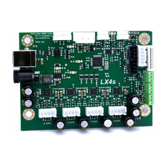
Page 6: Base Board Diagram And Connector Functions
LX4s Series Base Board diagram and connector functions Note: Pin 1 is marked with an ⓯ ⓮ ⓭ ⓬ ⓫ ❶ ❿ ❷ ❾ ❽ ❼ ❺ ❻ ❹ ❸... -
Page 7: Connector Definitions And Pinout Information
14. LPAL Laser Power & PWM connector Pin 1 – Laser Output Pin 1 – +24V Pin 2 – Laser +5V Power (used for laser output pull up) Pin 2 – Output Pin 3 – Ground Pin 3 – Ground Pin 4 –... -
Page 8: Base Board Diagram And Led Locations
LX4s Series Base Board diagram and LED locations �� �� �� �� ��... -
Page 9: Led Definitions And Functions
LX4s Series LED definitions and functions Reverse Polarity LED Done/Active LED If the voltage is reversed the red led will This led indicates GRBL is running and illuminate and prevent the board from also turns off and on when settings are powering up updated 24V Power LED... -
Page 10: Hardware Installation
LX4s Series Hardware Installation This procedure is for an M2 Nano controller board replacement in a K40 or other laser engraver. Since there are many variations of wiring schemes used in different laser engravers this procedure will only cover how to swap out the M2 Nano board and replace it with the Laser GBRL LX4s board. - Page 11 LX4s Series “Ribbon cable” configuration 1: Ribbon Cable Contacts Side...
- Page 12 LX4s Series “Discreet wire” configuration 2: Ribbon Cable Contacts Side...
- Page 13 LX4s Series “Discrete wire” configuration 3: Do not use. Cover connector to isolate.
- Page 14 4. Take note of which configuration you have above and begin by removing the cables from the board. When the cables are removed you are now ready to remove the M2 Nano frame from the laser engraver. Pictured here is a K40. If your setup differs from a K40 consult your manual for details on how to remove your board from your laser engraver.
- Page 15 LX4s Series 6. Once you have removed the M2 Nano board from the frame or other panel, get your new Laser GRBL LX4s board and fasten it to the same frame or other panel in your laser engraver using the hardware (M4 screws, spacers and nuts) that was previously used to fasten the M2 Nano board.
-
Page 16: Hardware Settings And Software Installation
When you are ready, connect the provided USB cable “A” plug into an available USB 2.0 or USB 3.0 port on your PC and the cable “B” plug into the Laser GBRL LX4s board. DO NOT connect the power cable into the board at this time. -
Page 17: Lx4S Board Power Up And Initialization
DC connector to the DC jack on the board FIRST, then connect the AC power cord and then plug the power cord into the wall outlet. Turn on your laser. The board gets 5V power from the laser power supply. -
Page 18: Lightburn Device Setup
LX4s Series LightBurn Device Setup Find and run LightBurn software by double clicking the icon on the desktop or find it in the start menu. Once open click on Devices button: 2. Once you click on the Devices button you will see a Devices window appear. Since this is a new installation and there are no devices in the Device List you will need to click on the Create Manually button as shown:... - Page 19 LX4s Series 3. Once you have clicked on Create Manually button another window will appear. Choose GRBL-LPC and then Next as shown: 4. Next another window will appear. Click Next as shown:...
- Page 20 Please see page 47 for more information. MUST 6. The next window that appears will ask for the origin of the laser (the origin Front Left as shown below. Any other option will not work. LightBurn is a positive only coordinate system).
- Page 21 LX4s Series 7. Finally, we should see this window when the device has been configured. Click Finish to complete the Device Setup: This concludes the Device Setup. If this has been completed successfully proceed to the next section. If the device setup has not completed successfully or if you have questions, please contact Vms for further assistance.
-
Page 22: Connecting To The Lx4S Board
LX4s Series Connecting to the LX4s Board 1. To connect to the LX4s board click the “Choose” dropdown as shown below and select the com port the LX4s board is connected to. If the drivers were installed correctly the dropdown will automatically populate the com port numbers when LightBurn loads. -
Page 23: Machine Jog X & Y Direction Setup
Right, Up and Down direction buttons circled below. DO NOT jog the laser head in rapid succession or you may lock up the board. Wait for the laser head to complete each “jog” movement before pressing jog again. If the machine jogs in the wrong direction you will need to adjust the axis direction in the machine settings. - Page 24 LX4s Series 2. If the X or Y axis direction is wrong you will need to change the settings for that axis. To change the machine settings, go to Edit and then Machine Settings as shown below:...
- Page 25 LX4s Series 3. Once you click on Machine Settings a properties window will appear. Expand “Outputs setup” by double clicking on it. You will see the X Direction pin invert and Y Direction pin invert as shown below. To change the direction, click on the True or False switch. When you are finished making changes click OK:...
-
Page 26: Y Limit Switch Testing
X & Y Limit Switch Testing 1. In order for the laser engraver to home properly you need to ensure the limit switches are working properly. To get a status of the limit pins go to the Console tab and type “?” then... - Page 27 OR press the mechanical micro switch (commonly found in some K40’s and other laser engravers) for that axis one at a time ensuring the limit switch stays triggered then type “?” and press Enter. Run this test for the X and Y axis.
-
Page 28: Homing Direction Setup And Homing
In order to adjust the homing direction, you will need to know where the home location is. For most laser engravers the homing location is in the Rear Left or the Rear Right. For custom laser engravers the homing location can also be located in the Front Left or even the Front Right. - Page 29 If the X or Y axis go in the wrong direction shut down the laser immediately. Wait for about ten seconds and then turn the laser back on, check the settings and re-home.
-
Page 30: Workspace Offset Setup
LX4s Series Workspace Offset Setup In order for the LX4s board to work well with LightBurn the offsets have to be applied correctly. The LX4s board works like most CNC controllers and uses the positive and negative coordinate system. LightBurn uses positive workspace coordinates only. To get around this we need to apply offsets. - Page 31 LX4s Series 3. To apply the offsets, we will use the same example above. Find your home location (on the left) Rear Right, Rear Left, Front Right and Front Left. Pick ONLY ONE location and then enter the string to the right under Offset Command in the LightBurn Console command field then press Enter: Home Location: Offset Command:...
-
Page 32: Steps Per Mm Calibration For X And Y Axes
LX4s Series Steps per mm calibration for X and Y axes The board is loaded with default values of 80.000 steps per mm for the X and Y axes. Most lasers use the 0.9° motors. If your motors are 1.8° then the default value needs to change to 40.000 steps per mm for the X and Y axes. -
Page 33: Laser Power Calibration Procedure
(mA) line up as shown in the red box below (Example 1B). For example, if you have a K40 and the laser tube is 40W then the range in current is 12mA – 0.24mA. Keep in mind the mA meter itself has a tolerance of 2.5 so the values may be a little off but within the mA meter’s... - Page 34 Keep adjusting $36 down until ALL mA values mostly line up. Some laser power supplies will not fire below 10 - 20%. The best way to run the calibration is to write down the values as the laser progresses through the lines. Shown below is an example (Example 1A) of what I have done. $36...
-
Page 35: Rotary Setup And Use
5. Go to Tools and then Rotary Setup. Select Roller, Enable Rotary, select the A-axis and then enter the Roller Diameter which should be 52.200mm for V1, V2 or V3 rotaries from HM Laser Accessories (Randy Smith) and then click OK. -
Page 36: Z-Bed Setup And Use
LX4s Series Z-Bed Setup and Use The Z-Bed is custom and requires building or purchasing one. There are quite a few designs on the internet for the K40 and can be scaled up or down to suit your particular bed size. One z-bed that I recommend is: https://gitlab.com/armoredblood/lazr_bed This design is very well documented and has a bill of material to order parts. -
Page 37: Going Further
LX4s Series Going further Congratulations you have successfully setup the LX4s Board with LightBurn! You are now ready to explore the LX4s board’s capabilities. If you have technical related questions or issues regarding the use of LightBurn there is a technical support forum which can be found here: https://forum.lightburnsoftware.com Or you can learn more about how to use LightBurn through videos on YouTube!! -
Page 38: Troubleshooting Lx4 Board And Lightburn
4. LX4 board is unresponsive and status bar is green with “Busy” • Right click on “Devices” button in the Laser section to do a soft reset of the LX4 board or press the reset button located next to the power connector on the board. -
Page 39: M7 & M8 Solid State Relay Control Outputs
LX4s Series M7 & M8 Solid State Relay Control Outputs The LX4s board has two solid state relay outputs to control air assist, exhaust fan, auxiliary device or function. You can control M7 or M8 through LightBurn for automatic air assist. To set M7 or M8 go to LightBurn Device Settings and choose which one you would like to use: NOTE: You can also test M7 and M8 through the LightBurn console. - Page 40 LX4s Series Below is a sample connection to these two connectors and to the solid-state relay: The solid-state relay used in the diagram is the Fotek SSR-25 DA. Another similar solid-state relay that can be used is the TWTADE SSR-25DA. Both of these solid-state relays can control AC loads. If you need to control a DC load, use the TWTADE SSR-25DD.
-
Page 41: Laser Power Control Output
LX4s Series Laser Power Control Output The laser control output connector LP is controlled by a grbl setting $37 and can be accessed through the LightBurn console. Each board comes with a red cable assembly PN: 120096. Refer to *** $37 Laser Power Control below for more information. -
Page 42: X, Y & Z Limit Inputs
LX4s Series X, Y & Z Limit Inputs The LX4s Board has X, Y and Z limit inputs and they are on connectors XY LIMIT and Z LIMIT. The connections are wired as shown below:... -
Page 43: Jst Xhp Connectors And Part Numbers
LX4s Series JST XHP Connectors and Part Numbers The LX4 Board uses the JST type XHP style connectors for its interconnect standard. There are other Chinese brands that can be purchased from Amazon if desired to terminate your own cables. Below is an example of the XHP connector and the pin #1 mark. -
Page 44: Jst Vhr Connector And Part Number
IWISS SN-28B Crimping Tool NOTE: Since this housing and the crimp contacts usually come with the laser and the power supply wiring is already terminated this is mostly not required but in rare cases this is needed to use the LX4... -
Page 45: Grbl Settings And Definitions
DO NOT CHANGE. Default 1 $32=1 Laser Mode DO NOT CHANGE. 1 Enable, 0 = Disabled $33=20000 Laser PWM Frequency Change to suit your laser power supply frequency $34=0.0 Laser PWM off value DO NOT CHANGE. Default 0 $35=0.0 Laser PWM minimum value *Default 0.0. - Page 46 ** $35 Laser PWM minimum value This sets the laser PWM minimum value in a percentage between 0 to 100%. If this value is set to zero then the laser PWM turns off prematurely leaving gaps in corners or in text. This setting is beneficial for vector engraving or cutting.
- Page 47 This sets the laser power control in a percentage between 0 to 100%. For example, if the laser power is set to 0% = 0V, 50% = 2.5V and 100% = 5V. The laser power is adjustable to any range in between 0 and 100% with fractional percentages supported which means you can write for example 42.6% laser...
-
Page 48: Revision History
Updated the GRBL settings and added a new menu command “$S”. Added Laser Power Calibration section. Changed the order of the XY calibration and laser power calibration sections so it flows with the rest of the manual. Changed the wording for homing location, changed 80W mA to 20 and made some other small textual changes.
Need help?
Do you have a question about the GRBL LX4s and is the answer not in the manual?
Questions and answers
what is the best graphics format for the 55 RGBL Laser
как гравировать на цилиндре