Table of Contents
Advertisement
Quick Links
Advertisement
Table of Contents

Subscribe to Our Youtube Channel
Related Manuals for MBS UGW X Series


Summary of Contents for MBS UGW X Series
- Page 1 MANUAL Universal gateways...
-
Page 2: Table Of Contents
Table of contents Table of contents 1 Introduction ..................4 Registered trademarks ..................4 Copyright ........................4 Product support ...................... 4 Target group ......................4 2 Concepts, functions and gateway design ........5 Universal gateways ....................5 Classification of protocols ................... 6 Function and properties of data points ............ - Page 3 Table of contents 7 Appendix ..................... 66 FAQs ........................66 UGW X-series Introduction 3 of 66...
-
Page 4: Introduction
Conditioning Engineers, INC. (ASHRAE) • CANopen®, MODBUS® and LON® are registered trademarks of the respective trademark owners in certain countries. Copyright ©2020 MBS | Römerstraße 15 | 47809 Krefeld, Germany Phone: +49 2151 7294-0 Fax: +49 2151 7294-50 E-mail: info@mbs-solutions.de Website: www.mbs-solutions.de All rights reserved. -
Page 5: Concepts, Functions And Gateway Design
2 Concepts, functions and gateway design Concepts, functions and gateway design Universal gateways A gateway enables communication between devices which use different communication protocols (data exchange). The job of universal gateways is to connect data points of one network technology with data points of a large selection of other technologies. -
Page 6: Classification Of Protocols
2 Concepts, functions and gateway design 2.2 Classification of protocols Protocols can be classified according to several criteria. These properties must be considered part of using the gateway. Table 1: Protocol properties Topology Point-to-point A point-to-point connection is the connection between two connection communication partners. - Page 7 2 Concepts, functions and gateway design Client-server relationship in relation to data points In a client-server relationship, a server provides data to connected clients. The server accepts requests from clients, and then sends the requested data. This client-server relationship can be transferred to the relationship of data points among one another.
-
Page 8: Mapping
2 Concepts, functions and gateway design Data point type as part of address To be able to use the address to derive specified information concerning possible uses, the address contains a code letter. With this, the direction of data flow and the type of values are determined. The four most important data point types are covered below. - Page 9 2 Concepts, functions and gateway design dispatch file. The address of the target data point is registered on another line under the keyword target =. Example of a dispatch.txt file: # Mapping of a 1-bit value from Profinet to MODBUS [1190.M pnetd outbit 1.7] target = 80.S mod 3 coil 4 # Mapping of an analogue value from Profinet to MODBUS...
-
Page 10: Configuration And Project Planning
2 Concepts, functions and gateway design 2.5 Configuration and project planning 2.5.1 Control via text files The gateway is configured using text files. For each driver, there is a file (*.cfg) with communication parameters (e.g. baud rate) and a file (*.txt) in which the driver-specific data points are defined. The file named dispatch.txt contains the mappings of the data points of the various protocols. - Page 11 2 Concepts, functions and gateway design 2.5.2 Data point files The data points to be used and the properties these data points should have are determined in the data point file of each protocol. The file name is derived from a protocol-specific part of the name, a serial number, which is numbered in the event of multiple connections for the same protocol, and the extension *.txt.
- Page 12 2 Concepts, functions and gateway design Example configuration file MODBUS Slave modslave1.cfg [MODBUS-SLAVE] Baudrate = 19200 Databits = 8 Parity = even Stopbits = 1 Bustype = RS485 Protocol = RTU Timer = 100 BitCount = 255 WordCount = 16 RelaxedErrors = 1 ResponseTimeout = 4 SlaveTimeout = 300...
-
Page 13: Technical Design And Operating Principle
2 Concepts, functions and gateway design [140 protB parameter 29] target = 110 protA address8 Example mapping of a two-stage actual value (1 = day, 2 = night) to two binary values Entry in file protA.txt Entry in file protB.txt Entry in file dispatch.txt [M address83] [S parameter 129]... - Page 14 2 Concepts, functions and gateway design General operating principle: A gateway generally consists of at least two device parts. In the following image, this is a Modbus master and a BACnet server, for example. • The Modbus master (RTU) polls the Modbus slave devices for their data points (blue circles). •...
-
Page 15: Status Led
2 Concepts, functions and gateway design 2.7 Status LED The gateway provides quick orientation of the current operational state via a two-colour status LED. The LED has the colours green and red and as a mixed colour orange. During system initialization, the LED lights up orange. -
Page 16: Overview Of The Ugw X-Series
3 Overview of the UGW X-series Overview of the UGW X-series SINGLE-X DOUBLE-X TRIPLE-X Standard An integrated hardware adapter Two integrated hardware adapters Scope of supply • Universal gateway • Pluggable screw terminals • Documentation/Manual Type label The type label attached to the casing includes the following information: •... -
Page 17: Type Overview Of The Ugw X-Series
3 Overview of the UGW X-series • 200 data points • 500 data points • 1,000 data points • 2,500 data points Web server With the integrated web server (web interface), you can configure the gateways using a web browser, save the configuration and call up statistics and documentation. -
Page 18: Casing And Connections
3 Overview of the UGW X-series TRIPLE-X The UGW DOUBLE-X is equipped with a 100-BaseT Ethernet port (IP, RJ45), two hardware adapters and either an RS232 port or an RS485 port (MS/TP). • LAN – 10/100 MBit Ethernet (RJ45) • Power –... -
Page 19: Device Views
4 Device views Device views Front view of the UGW SINGLE-X standard ① Power Green LED lights up when the power supply is activated. ② RX (RxD, RS485) Yellow LED lights up when the gateway is receiving data over the serial interface. ③... -
Page 20: Front View Of The Ugw Double-X (Lon)
4 Device views 4.2 Front view of the UGW DOUBLE-X (LON) ① LON status Green LED lights up during data traffic with the LON network. ② PWR. (power) Green LED lights up when the power supply is activated. ③ RX (RxD, RS485) Yellow LED lights up when the gateway is receiving data over RS485. -
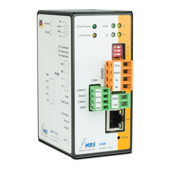
Page 21: Front View Of The Ugw Triple-X (Can + M-Bus)
4 Device views 4.3 Front view of the UGW TRIPLE-X (CAN + M-Bus) ① CAN power Yellow LED lights up when the power supply for the CAN bus (external) is activated. ② LON data Yellow LED lights up during data traffic with the CAN network. -
Page 22: Side View
4 Device views 4.4 Side view The following data and schematics are shown on the left-hand side of the casing of the UGW X-series and assigned to the functional elements on the front: • Designation and diagram of the positions of the LEDs and ports •... -
Page 23: Commissioning
5 Commissioning Commissioning To commission and configure the gateway, you will also need: • Power supply unit for the UGW • Computer • Installed web browser and PDF reader • Network cable The gateway provides an integrated web server for configuration. Chapter 5.2.1 describes the steps required to access the web server. - Page 24 5 Commissioning DIP switches S1, S2 and S3 have the following functions for network bias and termination resistance: S1 and S2: • Activate the network bias (defined 0 V or 5 V level on lines B+ and A-, even if no subscribers are actively transmitting). •...
- Page 25 5 Commissioning Connect the UGW to your PC with the network cable for configuration. Enter the IP address of the UGW web server in a web browser: http://169.254.0.1. Note: Note that your computer's LAN connection has to be set appropriately. For a manual setting, define the IP address as 169.254.0.2, for example.
-
Page 26: User Interface, Operation And Functions
6 User interface, operation and functions User interface, operation and functions When you have successfully logged in, you will see the gateway configuration page with an overview page. The upper menu bar is there for you to navigate this. Upper menu area The web interface contains the following menu areas for configuration of the gateway: •... -
Page 27: General" Menu
6 User interface, operation and functions 6.1 “General” menu 6.1.1 General > Overview After logging in, the universal gateway loads an overview page for the device. You can reload and update the page with the Update button. Type: UGW type display Name, installation location, description: This project-specific information, which can be modified, serves to identify the universal gateway. - Page 28 6 User interface, operation and functions Edit the input fields for this purpose. Important: To save the settings on the configuration pages, click on [Save]. An info dialogue then confirms the application of the entries. 6.1.3 General > IP network Configure the IP network settings on this configuration page.
- Page 29 6 User interface, operation and functions Services: Use the drop-down list Web server access to select which protocols to use to access the gateway in the network: • Active port 80 with unencrypted http protocol • Active port 443 with encrypted https protocol •...
- Page 30 6 User interface, operation and functions NTP time synchronization When using NTP time synchronization, the UGW takes its time from the specified NTP server. Evaluating BACnet time synchronization: The UGW listens for and evaluates sent BACnet messages for time synchronization. Note: Time synchronisation via BACnet can only be used if the BACnet driver is installed and if there is a time synchronisation master in the BACnet network.
- Page 31 6 User interface, operation and functions 6.1.5 General > Dropbox The dropbox function can be enabled as an option. Contact us or click [Request] to order this option by mail. 6.1.6 General > Web services The gateway offers web services for reading data point lists or changing data points. To activate web services, tick the Web services box.
- Page 32 6 User interface, operation and functions 6.1.7 General > Email Activate and configure the email service on this configuration page. 6.1.8 General > User management The password for the user “gw” can be changed on this configuration page. You also have the option to add additional users.
- Page 33 6 User interface, operation and functions Create gateway data backup: Use this option to generate a data back-up of the gateway configuration. Click [Start] and save the back-up file. The data back-up includes all the gateway's settings and is stored locally on your PC. Restore gateway data backup: When you select the Restore gateway data back-up option, the gateway reads an available data backup from your local data storage device and restores the configuration.
- Page 34 6 User interface, operation and functions 6.1.10 General > Update The UGW offers the following options for licence and software updates: • Request new licence • Upgrade licence • Update universal gateway system software • Configure driver Request new licence The current licence is displayed.
- Page 35 6 User interface, operation and functions As the recipient, enter support@mbs - solutions.de. The email should not be edited. Send the email with the Send command. Licence upgrade You can load the new licence with this tab. You will receive a licence file from the manufacturer of the universal gateway. This file must be located on your computer and is only valid for your device.
- Page 36 6 User interface, operation and functions Load the new firmware file in the input field with [Select file]. Transfer the file to the device with [Start]. Driver configuration Using this tab, you can configure the active drivers and specify the interfaces on which they run. UGW X-series User interface, operation and functions 36 of 66...
- Page 37 6 User interface, operation and functions 6.1.11 General > Restart Changing the configuration, importing a data backup or adjusting any other settings requires you to restart the communication software of the gateway. If the system needs to be restarted, this will pop up below the upper menu bar as a [Restart Required!] button.
-
Page 38: General Information On The Driver Menu Areas
6 User interface, operation and functions You can select two options (check boxes) for restarting: • Complete system restart (takes approx. 1 minute): Automatically selected when changing certain system settings. • Delete historical data Deletes all data collected up to this point, e.g. BACnet Trendlog data. This is necessary to conduct a smooth restart without collected test data during commissioning. -
Page 39: System" Menu Area
6 User interface, operation and functions You can scroll through the data point list with the arrow key. The Page size drop-down list allows you to define the maximum number of data points that can be displayed at the same time (10, 50, 100, 250 or 500). The Update drop-down list enables you to determine the time intervals at which the data point list is updated automatically (---, 5, 10, 15, 30 or 60 sec). - Page 40 6 User interface, operation and functions 6.3.1 System > Status The current statuses of gateway data points are displayed here and can be edited if necessary. Clicking the Info button will show the detailed properties of a data point. To edit the set value of a data point, click the Edit button. Enter the new set value in the Set Value dialog and confirm with [OK].
-
Page 41: Bacnet Menu
6 User interface, operation and functions 6.3.2 System > Settings You can make further driver settings on this configuration page. IgnoreFailure: So-called failure data points exist for communication devices. These show whether communication with a device is working (value 0) or if communication with a device is faulty (value 1). These data points are represented in the gateway’s status LED display. - Page 42 6 User interface, operation and functions 6.4.1 BACnet > Status This page displays the current statuses of all BACnet data points. These data points can be used for data point mapping. The Info button loads details on the data points. If necessary, you can change BACnet values using the Edit button.
- Page 43 6 User interface, operation and functions Start delay: Here, you can set a start delay for BACnet failure detection. When restarting the UGW, BACnet communication will only be switched on after this time has elapsed. This allows a remote station to recognise if the UGW has been restarted by the absence of BACnet requests.
- Page 44 6 User interface, operation and functions LAN name : Name of the data link interface UDP port Defines the UDP port of the BACnet/IP network as a decimal number. The default value is 47808 (“0xBAC0” – hexadecimal). IP mode: Defines the gateway’s IP mode for this data link. •...
- Page 45 6 User interface, operation and functions c) IP Mode = Foreign device The gateway is set as a foreign device subscriber to the BACnet network. IP address BBMD server: The IP address of the BBMD which is to be used by the UGW for logging in as a foreign device. UDP port BBMD server: You can define the UDP port of the BBMD server as a decimal number (default value: 47808 dec.
- Page 46 6 User interface, operation and functions Network number: Defines the network number of the BACnet network for the datalink. The value is between 1 and 65,534. MS/TP address: Defines the MS/TP MAC address. Max. master: The property Max. master defines the highest MAC address for master nodes in the MS/TP subnetwork.
- Page 47 6 User interface, operation and functions Device instance: Defines the device instance number of the gateway, which has to be unique within the overall BACnet network. The value range of this property is between 0 and 4,194,302. Device name: Defines the UGW device name, which also must be unique. Description: Defines the BACnet description of the UGW.
- Page 48 6 User interface, operation and functions APDU max segments accepted: Defines how many segments are accepted as a maximum. APDU segment timeout: This value defines the period of time after which an acknowledgement-dependent, segmented telegram is deemed to have failed in the absence of segment confirmation (default = 2,000 ms). 6.4.4 BACnet >...
- Page 49 6 User interface, operation and functions The status texts for the values “0” and “1” can be edited in the Inactive text and Active text input fields. For this object type, BACnet allows a “change-of-state counter” to be activated. The object is automatically extended to all object properties necessary for this purpose.
- Page 50 6 User interface, operation and functions These files can be transferred between the computer and the universal gateway (download/upload) on this page. The Edit buttons open text windows in which you can edit the relevant files directly. No further file transfers are required for this. Rows with a hash # at the beginning are comments.
-
Page 51: Modbus Master Menu
6 User interface, operation and functions 6.4.7 BACnet > EDE file The BACnet objects and functions configured in the gateway can be shared with other partner companies in projects in the form of a specified CSV file (EDE file, Engineering Data Exchange). To generate the EDE file automatically on this configuration page and then download it from the universal gateway to your computer, click [Start]. - Page 52 6 User interface, operation and functions 6.5.2 MODBUS Master > Settings You can edit general settings for the Modbus master driver on this configuration page. Rows with a hash # at the beginning are classified as comments. Rows without # at the beginning are activated settings.
-
Page 53: Lontalk" Menu Area
6 User interface, operation and functions Rows in the text dialogs with a hash # at the beginning are comments. Rows without # at the beginning are activated settings. Confirm the changes with [Save] and carry out a simple restart of the communication software. 6.6 “LONTalk”... - Page 54 6 User interface, operation and functions 6.6.3 LONTalk > Data points The LON data point configuration is displayed here. Data points can be filtered by category using the upper panel of buttons. The available LON data points are listed below. nviBindings and nvoBindings are the LON data points with which the mechanism of the LON binding can be used.
-
Page 55: M-Bus" Menu Area
6 User interface, operation and functions 6.6.4 LONTalk > Files The entire LONTalk configuration is saved in three files: lon1.cfg (driver); lon1.txt (data points); dispatch.txt (global dispatch file) These files can be transferred between the computer and the universal gateway (download/upload) on this page. - Page 56 6 User interface, operation and functions The data points can be used for data point mappings and for mapping BACnet objects, for example. The Info button loads details on the data points. Using the Edit button, you can activate or deactivate remote settings for the driver.
- Page 57 6 User interface, operation and functions Scan procedure The M-Bus scan is carried out in four steps (see the four tabs on the page): Scan settings: Make scan settings and start scan. 2. Scan result – Select counter: Selection and designation of identified counters or Profinet. 3.
- Page 58 6 User interface, operation and functions counter data. In the Name column, you can issue a unique name to each counter. Complete this step with [Save]. Step 3 – Select data points Next, the data points to be used for every previously selected counter are polled. To improve recognition, the data point values and units from the previous scan are displayed.
-
Page 59: Canopen" Menu Area
6 User interface, operation and functions 6.7.3 M-Bus > Settings On this page, you can make a host of settings for the M-Bus driver. The possible configuration of the parameters is described in the Description column. 6.7.4 M-Bus > Files The M-Bus configuration is saved in files. - Page 60 6 User interface, operation and functions 6.8.1 CANopen > Status This page shows the available CANopen data points. The data points can be used for data point mappings and for mapping BACnet objects, for example. 6.8.2 CANopen > Settings On this configuration page, you can edit the configuration file of the CANopen driver. Rows with a hash # at the beginning are classified as comments.
-
Page 61: Help Menu
6 User interface, operation and functions These files can be transferred between the computer and the universal gateway (download/upload) on this page. For the upload, a dialog opens in which you can select the file on the PC and transfer it with [Start]. - Page 62 6 User interface, operation and functions 6.9.2 Help > Open source licences “Start Download” makes a list of used open source components available on the universal gateway and their licences. 6.9.3 Help > Device info This page displays general information about the universal gateway. Type: Manufacturer’s internal hardware designation Protocol ID:...
- Page 63 6 User interface, operation and functions Data points: Number of data points used/Number of licenced data points Licenced drivers: Number of drivers which may be active at the same time: System start: Displays the last time the universal gateway was started. Free RAM: Size of used RAM and total RAM in MB Too little free space can lead to operational problems.
- Page 64 6 User interface, operation and functions 6.9.5 Help > Log files (System) You can activate/deactivate a more detailed version of the log records for each communication driver using the verbose buttons [ON] and [OFF]. Log records provide information on how the programme is running and any communication problems.
-
Page 65: Exiting The Web Interface
6 User interface, operation and functions 6.10 Exiting the web interface Click the button with the door symbol at the top right and confirm the logout dialog. 6.11 Reset – Options With the hardware-reset button, the device can also be reset Hard-Reset without calling up the configuration interface. - Page 66 7 Appendix Appendix FAQs Problem: You want to the access gateway, but do not know the IP address. Solution 1: The following solution applies only for gateways up to version 3_00_14. Starting with version 4_XX, the DHCP server is no longer implemented! If the computer is set as a DHCP client (default setting), you can use the DHCP server of the gateway to provide an IP address.
Need help?
Do you have a question about the UGW X Series and is the answer not in the manual?
Questions and answers