Advertisement
Advertisement
Table of Contents

Summary of Contents for Howden WRV
- Page 1 WRV & WRVi COMPRESSOR RANGE SERVICE MANUAL...
- Page 2 INDEX TO SECTIONS Page Number SECTION 1 FOREWORD SECTION 2 DESCRIPTION The WRV / WRVi Compressor Compression Cycle Gas System Oil System Oils SECTION 3 INSTALLATION Alignment of Compressor Couplings Alignment Tolerance Dowelling Piping SECTION 4 FIRST START UP First Start...
- Page 3 SECTION 1 FOREWORD...
- Page 4 001 610 313 9215 E-mail: hcl.aftersales@howden.com E-mail: parts@howdencompressors.com Website: www.howden.com Website: www.howden.com All enquiries should be accompanied by the Howden Compressors Contract Number and the Compressor Serial Number, taken from the nameplate on the side of the compressor body. HOWDEN COMPRESSORSCOMPRESSORS...
- Page 5 HOWDEN SECTION 2 DESCRIPTION...
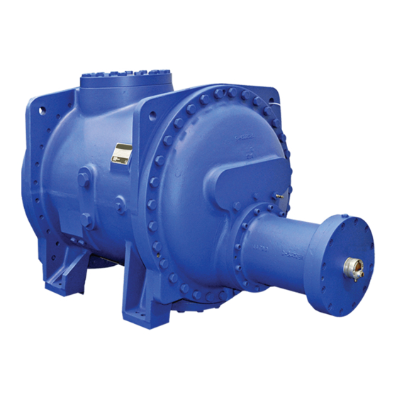
- Page 6 THE WRV COMPRESSOR The Howden WRV & WRVi Oil Injected Compressor is a positive displacement, capacity controlled, oil flooded, rotary machine. Compression is achieved by the meshing of two helical rotors on parallel shafts housed in a casing. The accurately machined helical rotors are called Male and Female. The Male (driving) rotor has four lobes which mesh with six flutes in the female (driven) rotor, both rotors having the same outside diameter.
- Page 7 THE COMPRESSION CYCLE (DIAGRAMMATIC ONLY) 1. Gas is drawn in to fill the As the rotors rotate, the interlobe space moves past interlobe space between the inlet port so sealing the interlobe space. adjacent lobes on top side of Viewed from the top side of rotors at Inlet End. rotors at Inlet End.
- Page 8 DESCRIPTION OF A GAS SYSTEM FOR A TYPICAL REFRIGERATION COMPRESSOR SET Gas is drawn into the compressor through a non-return valve and then a strainer is fitted directly on the inlet flange and discharged into an oil tank/separator. The non-return valve is necessary to prevent the compressor being “motored”...
-
Page 9: Recommended Lubricating Oils
Should you wish to review this matter, please do not hesitate to contact Howden Compressors Limited, who will be pleased to provide recommendations and costs for any special ‘O’ ring materials which may be required. -
Page 10: Installation
SECTION 3 INSTALLATION... - Page 11 ALIGNMENT OF COMPRESSOR COUPLINGS The couplings supplied with this compressor must be aligned using the method described below: If a compressor only is supplied the coupling alignment tolerance figures can be seen under Section 3.2. During alignment checks, both half couplings should be rotated together from 0° to 90°, 180°, 270° and 360°...
- Page 12 ALIGNMENT OF COMPRESSOR COUPLINGS (Continued) If the gap is checked with the couplings “hard together”, ie, in the normal running condition, it should be equal to the required coupling gap: 3.175mm (0.125”). NOTE: If a “limited float” coupling is used with an electric motor whose shaft has no thrust bearing, the gap must be correct with the motor shaft on its magnetic centre.
- Page 13 Note that the pipes and fitting used should not restrict flows. To avoid this always use piping with a bore ¼” larger than the thread diameter of the compressor port, eg, WRV 204 oil injection connection thread is ¾” BSP and so a 1” OD pipe should be used.
-
Page 14: First Start-Up
SECTION 4 FIRST START UP... -
Page 15: First Start
FIRST START Installation of the compressor will have been carried out in accordance with Section 3 of this manual. The Commissioning Engineer should however ascertain that the correct procedures have been followed, in particular the coupling alignment must be checked, then proceed as follows: Disconnect the coupling between the drive and the compressor and check that the direction of rotation is correct to drive the compressor in a clockwise direction, looking on the compressor input shaft. -
Page 16: Normal Operation
SECTION 5 NORMAL OPERATION... -
Page 17: Normal Start
NORMAL START Check the level of the oil in the tank. Check that all the necessary gas, oil and water valves are open. Start the lubricating oil pump motor. Ensure the capacity control valve is in the fully unloaded position. Start the drive unit and check that all gauges are indicating normal readings. - Page 18 SECTION 6 PROCEDURES DURING SHUTDOWN...
- Page 19 INHIBITING OILS APPROVED FOR USE WITH HOWDEN SCREW COMPRESSORS A list of approved inhibiting oils suitable for use on the Howden Screw Compressor prior to a prolonged shutdown is shown in Fig. 1.
-
Page 20: Maintenance
SECTION 7 MAINTENANCE... -
Page 21: General Comments
Special tools to ease dismantling and re-assembly can be provided, as listed in Section 9.3. Details of these can be obtained from the Compressor Business Unit, Howden Compressors. Section 10 details all Part Numbers of normally replaceable components. - Page 22 PREPARATION FOR ANNUAL INSPECTION Before dismantling the compressor, certain precautions should be taken in the interests of safety: Isolate the drive unit. Depressurise and purge the system. Disconnect the drive unit coupling from the compressor. Place a receptacle under the outlet end of the compressor to catch any oil which may drip from the hydraulic cylinder when the cylinder cover is removed or when the outlet end cover is removed.
- Page 23 DISMANTLING PROCEDURE FOR ANNUAL INSPECTION (Continued) Fig. 2 Fig. 3 NOTE: The indicator spindle has to clear a dowel pin which moves along the spiral groove in the spindle, therefore this cover must be kept in an axial position when withdrawing until the spindle clears the dowel pin (Fig 3).
- Page 24 DISMANTLING PROCEDURE FOR ANNUAL INSPECTION (Continued) Removing the Combined Outlet Cover/Cylinder 163 Compressor Fit an eyebolt to the tapped hole at the top of the outlet cover, attach a sling to the eyebolt to support the weight of the cover (Fig. 7). Fig.
- Page 25 DISMANTLING PROCEDURE FOR ANNUAL INSPECTION (Continued) Extract the set pins securing the discharge cover to the main casing body. (Fig. 8) Push the piston rod to the bottom of the cylinder. Carefully draw the cover clear of the piston rod/valve spindle. Care should be taken to prevent damage to the actuator cylinder which is part of the cover.
- Page 26 DISMANTLING PROCEDURE FOR ANNUAL INSPECTION (Continued) Removing the Cylinder and End Cover WRV204, WRVi255, WRVi321 & WRVi365 Compressors The hydraulic cylinder and end cover are separate items in the above compressor and are removed as follows: Removing the Hydraulic Cylinder Extract the cap screws or setscrews securing the cylinder to the end cover (Fig.
- Page 27 DISMANTLING PROCEDURE FOR ANNUAL INSPECTION (Continued) Fit an eye bolt to the top of the outlet cover flange and use suitable lifting equipment to support the weight of the cover (Fig. 15). Remove the set pins locating the cover to the main casing and remove the cover. Fig.
- Page 28 DISMANTLING PROCEDURE FOR ANNUAL INSPECTION (Continued) Now that the slide valve has been removed by shining a light from the valve bore, a visual inspection of the rotors can be achieved (Figs. 18 - 19). Fig. 18 Fig. 19 PTFE Seals. The compressor has now been dismantled enough to permit the inspection and replacement of the PTFE seals and ‘O’...
-
Page 29: Checking Clearances
CHECKING CLEARANCES Guide Block The guide block which locates the slide valve should also be checked for wear every 30,000 hours or every 4 years whichever comes first. See Fig. 22 and relative table for dimensions. Guide Block to Slide Valve Slot Compressor Size Fig. - Page 30 CHECKING CLEARANCES (Continued) To check the Thrust Bearing Float To check the thrust bearing float, set a dial indicator up axially on the shaft end. Access must be gained to the inlet end of the female rotor by removing the rotor cover. Push or pull the rotor, to its limit in either direction.
- Page 31 RE-ASSEMBLY AFTER ANNUAL INSPECTION When all checks and corrections have been made, and assuming no major problems have developed, the compressor can be re-assembled. (Refer to the Sectional Arrangement drawing supplied and torque specifications as advised under Section 9.1) WRV163 Compressor Ensure the guide block is in position in the slide valve bore, insert the slide valve and push it all the way to the ‘on load’...
- Page 32 REASSEMBLY PROCEDURE FOR ANNUAL INSPECTION (Continued) WRV204, WRVi255, WRVi321 & WRVi365 Ensure the guide block is in position in the slide valve bore, insert the slide valve and push it all the way to the on load position (Fig. 28). Insert an eyebolt into the outlet end cover flange and with the aid of suitable lifting equipment re- assemble the outlet end cover and secure (Fig.
- Page 33 SECTION 8 OVERHAUL...
-
Page 34: General Procedures
GENERAL PROCEDURES Although a yearly inspection and maintenance programme is recommended if no condition monitoring equipment is fitted, it is essential that a major overhaul is carried out after approximately 4 years operation or earlier, dependant on site conditions. To carry out a major overhaul proceed as follows: If necessary, isolate, depressurise and purge the system. - Page 35 DISMANTLING 163 COMPRESSOR FOR MAJOR OVERHAUL The compressor to be dismantled as per procedures for Annual Inspection under Section 7.3 then proceed: Checking Journal Bearing Clearance (163mm) At this point in the dismantling procedure the journal bearing clearance should be checked to determine whether the journal bearings need to be replaced as part of the compressor overhaul.
- Page 36 DISMANTLING 163 COMPRESSOR FOR MAJOR OVERHAUL (Continued) Repeat the procedure on both rotors. If there is any doubt about the clearance of a bearing, renew the bearing. As the inlet end bearings are more lightly loaded they then only require to be inspected if the outlet end bearings require to be replaced.
- Page 37 DISMANTLING 163 COMPRESSOR FOR MAJOR OVERHAUL (Continued) Removing the Inlet Shaft Seal (163mm) Withdraw the driven half coupling key from the input shaft. Extract the cap screws (Fig. 40) from the shaft seal cover and, using the jacking screw holes provided in conjunction with the T-bar jacking tools, remove the shaft seal cover.
- Page 38 DISMANTLING 163 COMPRESSOR FOR MAJOR OVERHAUL (Continued) Removing the Inlet End Cover (WRV163mm) Fit an eyebolt into the tapped hole at the top of the inlet cover flange. Attach a sling to the eyebolt and support the weight of the cover using some form of lifting gear (Fig. 43).
- Page 39 DISMANTLING 163 COMPRESSOR FOR MAJOR OVERHAUL (Continued) Removing the Rotors (163mm) Now that the inlet and outlet end casings and the thrust bearings have been removed as described previously, the rotors can be withdrawn from the main casing as shown in Figs.46-47. See table Fig. 48 for estimated rotor weight.
- Page 40 Fig. 51. Adjustment, if necessary, is carried out by machining of the thrust bearing withdrawal plates. Fig. 49 Fig. 50 Rotor Outlet End Maximum Clearance Allowable 163 Compressor Clearance 0.050/0.075mm 0.100mm 0.002/0.003” 0.004” Fig. 51 WRV 163 Outlet End Clearance...
- Page 41 RE-ASSEMBLY 163 COMPRESSOR AFTER OVERHAUL (Continued) When the clearances are finalised, the retaining cap screws on the Thrust Retaining Plate should be wire locked using the following method: The grade of wire used should be 1/16” diameter Annealed S.S. Safety Wire. Adjustment, if necessary, is carried out by machining of the adjusting plate behind the thrust bearings (Fig.
- Page 42 DISMANTLING WRV204, WRVi255, WRVi321 & WRVi365 COMPRESSORS FOR MAJOR OVERHAUL The compressor to be dismantled as per procedure for Annual Inspection under Section 7.2, then proceed: Checking Journal Bearing Clearance (WRV204) As per procedure for WRV163 Section 8.2 Checking Journal Bearing Clearance (WRVi255, WRVi321 & WRVi365) Slacken back the set pins securing the thrust housing end cover, to ensure it is not binding on the outer rim of the thrust bearing (Figs.
- Page 43 DISMANTLING 204, 255, 321 & 365 COMPRESSOR FOR MAJOR OVERHAUL (Continued) If the journal bearing clearance inspection shows the bearing diametrical clearance is less than the maximum allowable, (see Fig. 55), the advantages of a further period of trouble free running with new journal bearings should be considered before deciding to re-use the existing bearings.
- Page 44 DISMANTLING 204, 255, 321 & 365 COMPRESSOR FOR MAJOR OVERHAUL (Continued) Removing the Input Shaft Seal (Continued) Pull out the shaft seal, taking care not to damage the carbon face of the seal. (Fig. 57) Withdraw the inlet balance piston using T-bar jacking tools in the jacking holes provided. (Fig. 58) Follow this up by removing the stationary seat from the seal cover.
- Page 45 DISMANTLING 204, 255, 321 & 365 COMPRESSOR FOR MAJOR OVERHAUL (Continued) Removing the Inlet End Cover (Continued) Remove the rest of the set pins and carefully slide the inlet cover over the extended shaft of the male rotor taking the ‘O’ ring seal with it (Figs. 60-61). Removing the Rotors In preparation for removing the rotors, unlock the thrust bearing lockwasher (Fig.
- Page 46 DISMANTLING 204, 255, 321 & 365 COMPRESSOR FOR MAJOR OVERHAUL (Continued) Fig. 64 Fig. 65 Estimated Weights Rotor Male Female Size 204/1.10 204/1.65 255/1.10 255/1.65 255/2.20 321/1.32 321/1.65 321/1.93 365/1.65 Fig. 66 365/1.93 1111 Fig. 67. Rotor Weights The thrust bearing sleeves and the angular contact thrust bearings can now be easily removed. The balance piston and balance piston sleeves are now accessible and, with the aid of the screwed ‘T’...
- Page 47 RE-ASSEMBLY WRV204, WRVi255, WRVi321 & WRVi365 COMPRESSORS AFTER OVERHAUL When repair or rectification work has been completed, the compressor should be assembled as follows: 1. Lubricate the bearing bores with lubricating oil and lift in the rotors, ensure the lobes mesh at the serial numbers on the rotors.
- Page 48 RE-ASSEMBLY WRVi255, WRVi321 & WRVi365 COMPRESSORS AFTER OVERHAUL (Continued) Checking Rotor Outlet End Clearance Insert the jacking screw into the holes provided on the bearing housing flange and lightly tighten the jacking screws until resistance is felt. The action of tightening the jacking screws draws the rotors against the outlet face of the main casing.
- Page 49 RE-ASSEMBLY WRV204, WRVi255, WRVi321 & WRVi365 COMPRESSORS AFTER OVERHAUL (Continued) Re-assemble the Outlet End Cover and Hydraulic Cylinder Re-assembly as described per Section 7.5 for WRV204, WRVi255, WRVi321 & WRVi365 compressors. Then proceed: Re-assemble the Vi Cover WRVi255, WRVi321 & WRVi365 Compressors. Pull Vi adjusting screw until the nut is against the inlet cover.
-
Page 50: Special Instructions
SECTION 9 SPECIAL INSTRUCTIONS... - Page 51 TORQUE SPECIFICATIONS Fig.73 Torque Specifications for Fasteners on WRV163 compressors. PART NUMBER TYPE OF FASTENER TORQUE lb ft TORQUE Nm 40mm Locknut R25055 Actuator Piston ¼” UNC x 5/8” Long Set Screw G26019 Piston Seal Retaining Plate M12 x 60 Long Capscrew M0216050 Cylinder to outlet cover ½”...
- Page 52 TORQUE SPECIFICATIONS (Continued) Fig. 75 Torque Specifications for Fasteners on WRVi255 compressors. PART NUMBER TYPE OF FASTENER TORQUE lb ft TORQUE Nm R25055 40mm Locknut Actuator Piston ¼” UNC x 5/8” Long Set Screw G26019 Piston Seal Retaining Plate M0212045 M12 x 45 Long Capscrew Cylinder to outlet cover M0116070...
- Page 53 TORQUE SPECIFICATIONS (Continued) Fig. 77 Torque Specifications for Fasteners on WRVi365 compressors. PART NUMBER TYPE OF FASTENER TORQUE lb.ft TORQUE Nm VR36148-2 45mm Locknut Actuator Piston 3/8”UNC x 1” Long Set G21026 Screw Piston Seal Retaining Plate M0216060 M16 x 60 Long Capscrew Cylinder to outlet cover M0124100 M24 x 100 Long Set Screw...
- Page 54 PROCEDURE FOR FITTING LOCKWASHERS This instruction applies to all lockwashers used on Howden Compressors, for the purpose of retaining, in position, the locknuts locating the bearings, thrust collars, pistons, etc. A typical example of the items concerned is shown below (Fig.105).
-
Page 55: Special Tools
SPECIAL TOOLS Tools can be provided for ease of dismantling/assembly. However, they are not a mandatory requirement. WRV163 Compressor Tools Part No. Locknut Spanner 30mm for Valve Spindle 19274J Locknut Spanner 40mm for Piston 19187J Locknut Spanner 50mm for Thrust Bearing 17916J Piston Withdrawal Gear 163045J... - Page 56 SPECIAL TOOLS (Continued) WRVi 321 Compressor Tools Part No. Jacking Plate for Rotor Removal when using a 32919J Hydraulic Jack Extractor for Balance Pistons 32920J Extractor for Inlet Balance Piston Sleeve and 32921J Mechanical Seal Locknut Spanner for Piston – (WRVi321 Only) 32922J T-Screws for Extraction purposes 5/8”...
- Page 57 SECTION 10 SPARES...
- Page 58 10.1 WRV WRVi RECOMMENDED SPARES LIST Spares are available for all WRV compressors in the form of the following kits: SHAFT SEAL KIT Shaft seal and cover ‘O’ Ring ANNUAL INSPECTION KIT All ‘O’ Rings and seals required for an annual inspection.
- Page 59 Inlet End Journal Bearing Dowel Pin ¼” G34045 Note: For Viton or Fluorosilicone ‘O’ Rings please contact: Howden Compressors Limited, Compressor Business Unit, 133 Barfillan Drive, Glasgow, G52 1BE, UK Telephone: +44 (0)141 882 3346 Fax: +44 (0)141 882 8648...
- Page 60 RECOMMENDED SPARES LIST HOWDEN COMPRESSOR MODELS: Mk6 6A & 6B WRV(H) 204/110, 145, 165 & 193 Replacement Shaft Seal Kit – KS204 PART NUMBER DESCRIPTION QUANTITY Input Shaft Seal c/w Cover ‘O’ Ring KWS204 Annual Inspection Kit – KW204-6 PART NUMBER...
- Page 61 RECOMMENDED SPARES LIST HOWDEN COMPRESSOR MODELS: Mk6 & 6A 6B WRVi 255/110, 130, 145, 165, 193 Replacement Shaft Seal Kit – KS255-6 PART NUMBER DESCRIPTION QUANTITY Input Shaft Seal c/w Cover ‘O’ Ring KWS255-6 Annual Inspection Kit – KW255-6 PART NUMBER...
- Page 62 R32083 Outlet End Journal Bearing G36013 Dowel Pin Note: For Viton or Fluorosilicone ‘O’ Rings please contact: Howden Compressors Limited, Compressor Business Unit, 133 Barfillan Drive, Glasgow, G52 1BE, UK Telephone: +44 (0)141 882 3346 Fax: +44 (0)141 882 8648...
- Page 63 RECOMMENDED SPARES LIST MODELS Mk1 WRVi 365, ALL L/D’S Replacement Shaft Seal Kit – KWS365 PART NUMBER DESCRIPTION QUANTITY Input Shaft Seal c/w Cover O’ring XR12112-3 KWS365 Annual Inspection Kit – KW365 PART NUMBER DESCRIPTION QUANTITY Tab Washer ¾” G32020 Tab Washer 7/16”...
- Page 64 Printed in the UK – Issue HCL/September 2012 © Howden Compressors Limited...
Need help?
Do you have a question about the WRV and is the answer not in the manual?
Questions and answers