Table of Contents
Advertisement
Quick Links
Advertisement
Table of Contents
Troubleshooting

Subscribe to Our Youtube Channel
Summary of Contents for KEHUA TECH MR33120
- Page 1 Uninterruptible Power Supply MR33120 User Manual...
- Page 3 Copyright © Kehua Data Co., Ltd. 2021.All rights reserved. No part of this document may be reproduced or transmitted in any form or by any means without prior written consent of Kehua Data Co., Ltd. Trademarks and Permissions and other Kehua trademarks are trademarks of Kehua Data Co., Ltd. All other trademarks and trade names mentioned in this document are the property of their respective holders.
- Page 4 Summaries Thank you for choosing the UPS! This document gives a description of the MR33120, including the features, performance, appearance, structure, working principles, installation, operation and maintenance, etc. Please save the manual after reading, in order to consult in the future.
- Page 5 Uninterruptible Power Supply MR33120 User Manual Foreword Symbol Description Provides a tip that may help you solve a problem or save time. Provides additional information to emphasize or supplement important points in the main text. Product standard: Q/ZZKJ 007 All rights reserved ©Kehua Data Co., Ltd.
-
Page 6: Table Of Contents
Uninterruptible Power Supply MR33120 Contents User Manual Contents 1 Safety Description......................... 1 1.1 Safety Announcements ............................. 1 1.1.1 Safety Instructions ..........................1 1.1.2 Use Announcements for Battery ......................4 1.1.3 ESD Protection ............................5 1.1.4 Grounding Requirements ........................5 1.1.5 Warning Mark Setting ..........................5 1.2 Operation and Maintenance Requirements ...................... - Page 7 Uninterruptible Power Supply MR33120 User Manual Contents 2.5.5 Surge Protection Device ........................30 2.5.6 Top Wiring Accessory ........................... 30 2.5.7 Battery Tripper Control Accessroy ......................31 2.6 Alarm Function ............................... 31 3 Installation............................ 41 3.1 Installation Process ............................41 3.2 Installation Preparation ..........................42 3.2.1 Installation Tools ...........................
- Page 8 Uninterruptible Power Supply MR33120 Contents User Manual 4.5.2 Bypass Input ............................77 4.5.3 Battery Input ............................78 4.5.4 REC. Module ............................78 4.5.5 INV. Module ............................79 4.5.6 Output Information ..........................79 4.6 Set Manage ..............................80 4.6.1 Cabinet Set ............................81 4.6.2 Battery Set .............................
- Page 9 Uninterruptible Power Supply MR33120 User Manual Contents 5.3.3 Shut Down UPS ............................ 96 5.3.4 Switch to Bypass Mode Manually ......................97 5.3.5 Switch to Maintenance Bypass Mode From Mains Mode ..............97 5.3.6 Switch to Inverter Mode from Maintenance Bypass Mode..............98 5.3.7 Emergency Power Off (EPO) ........................
-
Page 11: Safety Description
Uninterruptible Power Supply MR33120 User Manual 1 Safety Description 1 Safety Description This chapter introduces the safety announcements. Prior to performing any work on the UPS, please read the user manual carefully to avoid human injury and device damage by irregular operations. - Page 12 Uninterruptible Power Supply MR33120 1 Safety Description User Manual Don't touch terminals or conductors that connected with grid to avoid lethal risk! Device damage or device fault may cause electric shock or firing! Before operating, please inspect the device and see if there is any damage or exist other danger.
- Page 13 Uninterruptible Power Supply MR33120 User Manual 1 Safety Description Do not reversely connect the grounding wire and neutral wire, live wire and neutral wire, which will cause short circuit. It should be well grounded and the voltage between ground wire and neutral wire should be not more than 5V.
-
Page 14: Use Announcements For Battery
Uninterruptible Power Supply MR33120 1 Safety Description User Manual When UPS is powered off, there still exists dangerous voltage. It should affix warning labels away from UPS location and the warning labels should include: 1. It supplies power for UPS. 2. Please disconnect UPS before wiring. -
Page 15: Esd Protection
Uninterruptible Power Supply MR33120 User Manual 1 Safety Description 1.1.3 ESD Protection To prevent human electrostatic damaging sensitive components (such as circuit board), make sure that you wear a anti-static wrist strap before touching sensitive components, and the other end is well grounded. - Page 16 Uninterruptible Power Supply MR33120 1 Safety Description User Manual The related operation and wiring for the UPS should be performed by qualified professionals, and ensure the electrical installation accords with the electrical installation standards. The installation and maintenance man should be trained, know about each safety announcement, get the right operation method, and then, the installation, operation and maintenance can be done.
-
Page 17: Environment Requirements
Uninterruptible Power Supply MR33120 User Manual 1 Safety Description Changing the UPS configuration, structure or assembly will affect the performance of the UPS. If user needs to do like this, please consult the manufacturer in advance. 1.3 Environment Requirements Do not put the UPS in the environment where has inflammable, explosive gas or smog. Don't do any operation in this environment. -
Page 18: Overview
MR means the modular UPS Figure2-1 Model meaning MR33120 has four power modules and a redundancy slot. UPS can select a redundancy module to improve UPS reliability. The detailed configuration is as shown in Table2-1. All rights reserved ©Kehua Data Co., Ltd. -
Page 19: Features
Uninterruptible Power Supply MR33120 User Manual 2 Overview Table2-1 Configuration description Item MR33120 Switch configuration Full configuration(4 pieces) 30K power module 4*30K Redundancy module 1 piece slot Power module height Bypass module height UPS dimensions(mm) 600*860*2000 Bottom wiring in default. It's compatible with top wiring(select the top Wiring method wiring component). - Page 20 Uninterruptible Power Supply MR33120 2 Overview User Manual Completely digitalized DSP control Adopt the completely digitalized DSP control for the inverter control, phase synchronization, output current-sharing, logic control of the power module, which is with high precision, high speed and perfect whole system performance.
-
Page 21: Working Principle
Power module N Figure2-2 Schematic diagram 2.3.2 Working Mode The MR33120 has four work modes: normal mains power supply mode, battery power supply mode, bypass power supply mode and maintenance bypass power supply mode. Normal mains power supply mode When the mains is normal, AC power is transformed to DC power by PFC, and supplies power for inverter. - Page 22 Uninterruptible Power Supply MR33120 2 Overview User Manual When the mains power supply is normal, the rectifier inside the power module will rectifier the mains to a positive and negative DC voltage, and the DC voltage gets through the inverter and then will output a stable 220Vac AC voltage to supply power for the load.
-
Page 23: Appearance And Structure
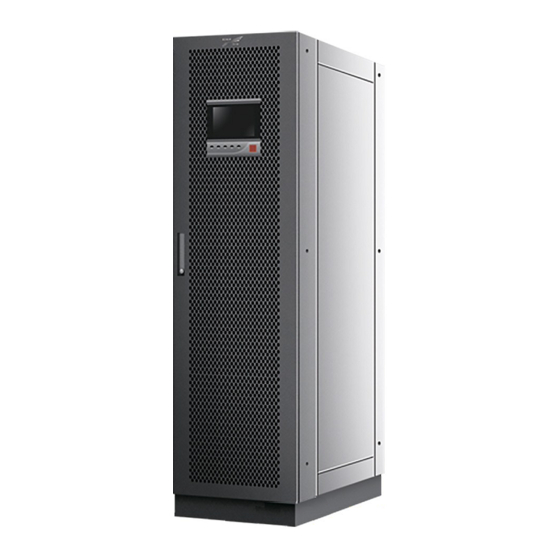
2.4 Appearance and Structure 2.4.1 Appearance The MR33120 consists of cabinet, operation panel, power module, bypass module, system control box, distribution unit, etc. The appearance of the MR33120 is as shown in Figure2-3. Figure2-3 Appearance All rights reserved ©Kehua Data Co., Ltd. - Page 24 Uninterruptible Power Supply MR33120 2 Overview User Manual Operation Panel Figure2-4 Operation panel Table2-2 Illustration of the operation panel Name Illustration ○ Touch screen Human-machine interactive interface On (green): The rectifier works normally. ○ AC/DC indicator On (red): The rectifier works abnormally.
-
Page 25: Structure Layout
Uninterruptible Power Supply MR33120 User Manual 2 Overview 2.4.2 Structure Layout The structure layout of the MR33120 is as shown in Figure2-5. Figure2-5 Structure layout of MR33120(open front door) Power module Power module height: 2U Dimensions(H× W× D): 86mm× 500mm× 700mm(include hangers and handles) ... - Page 26 Uninterruptible Power Supply MR33120 2 Overview User Manual Table2-3 Illustration of the operation panel of the power module Name Illustration On: Power module stays in inverter status. ○ RUN indicator (green) Flicker: Power module stays in standby status. ALARM indicator ○...
- Page 27 Uninterruptible Power Supply MR33120 User Manual 2 Overview Name Illustration ALARM indicator ○ On: Module input voltage abnormal, fan abnormal, etc. (yellow) ○ FAULT indicator (red) On: Module fault. Place the ready switch to “unlock” status, the indication color is green, the power module is not locked with the cabinet, and at this time, the bypass module can be ○...
- Page 28 Uninterruptible Power Supply MR33120 2 Overview User Manual Figure2-9 System control card Table2-5 Illustration of the system control card Name Illustration Realize the smart integrated display function. It is used for a UPS to monitor the running information of other parallel UPSs. The RS485 ○...
- Page 29 Uninterruptible Power Supply MR33120 User Manual 2 Overview 1--8 RJ45 RJ45 plug Pin definition: Pin 1:White orange-RS485:A 1 2 3 4 5 6 7 8 Pin 2:Orange-RS485:B Pin 3:White green-Reserved Pin 4:Blue-RS485:B 1 2 3 4 5 6 7 8 Pin 5:White blue-RS485:A...
- Page 30 Uninterruptible Power Supply MR33120 2 Overview User Manual Figure2-13 System monitor card There are two network ports on the system monitor card: MODBUS port and RS232 port. The MODBUS port is used for MODBUS communication, which is to communicate with upper computer.
- Page 31 Uninterruptible Power Supply MR33120 User Manual 2 Overview 1--8 RJ45 RJ45 plug Pin definition: Pin 1:White orange-RS232:TX 1 2 3 4 5 6 7 8 Pin 2:Orange-RS232:RX Pin 3:White green-Reserved Pin 4:Blue-RS232:TX 1 2 3 4 5 6 7 8 Pin 5:White blue-RS232:RX...
- Page 32 Uninterruptible Power Supply MR33120 2 Overview User Manual Port Mark Signal Illustration settable. Reinforced insulation ground External switch normal open When the NO and COM is short-circuit, the input port IN.1 signal is effective. This signal is settable. Reinforced insulation ground...
-
Page 33: Optional Accessory
When there isn't mains and bypass status, long press the battery cold start button for 2s and UPS will start in the battery status. 2.5 Optional Accessory The MR33120 UPS can select different accessories(as shown in Table2-9) to meet different requirements. All rights reserved ©Kehua Data Co., Ltd. -
Page 34: Snmp Card And Its Software
Uninterruptible Power Supply MR33120 2 Overview User Manual Table2-9 Optional accessory list Name Name SNMP card and its software Surge protection device Expansion card Top wiring accessory Parallel/BSC accessory Battery tripper control accessory Battery temperature sampling accessory 2.5.1 SNMP Card and Its Software SNMP card(as shown in Figure2-16) is installed in the UPS to realize the UPS remote management. - Page 35 Uninterruptible Power Supply MR33120 User Manual 2 Overview Green indicator(R) Status description Red indicator(E) Flicker Running OFF/ON Crash, keep final status. No alarm. Flicker Alarm * means the indicator is in any status. NETWORK port The NETWORK port adopts the RJ45 plug. The pin definition of the NETWORK port is shown in Figure2-17.
-
Page 36: Expansion Card
Uninterruptible Power Supply MR33120 2 Overview User Manual After finishing the SNMP installation and wring, please configure the software in the following order. Step 1 Open browser, and enter the IP address of the WiseWay built-in card (KC502)(Default IP is 192.168.0.100). - Page 37 Uninterruptible Power Supply MR33120 User Manual 2 Overview Figure2-18 Dry contact expansion card When the dry contact expansion card is selected, the dry contact expansion card will installed on the system control box of UPS before shipping. Table2-12 Illustration of the dry contact...
- Page 38 Uninterruptible Power Supply MR33120 2 Overview User Manual BMS expansion card The BMS expansion card(as shown in Figure2-19) is mainly used for the Li-battery communication. The BMS expansion card includes one BMS communication port, two input dry contacts and one output dry contact.
-
Page 39: Parallel/Bsc Accessory
Uninterruptible Power Supply MR33120 User Manual 2 Overview 1--8 RJ45 RJ45 plug Pin definition: Pin 1:White orange-BMS:A 1 2 3 4 5 6 7 8 Pin 2:Orange-BMS:B Pin 3:White green-Reserved Pin 4:Blue-BMS:B 1 2 3 4 5 6 7 8 Pin 5:White blue-BMS:A... -
Page 40: Battery Temperature Sampling Accessory
Uninterruptible Power Supply MR33120 2 Overview User Manual Figure2-22 Parallel system connection(multiple UPSs) 2.5.4 Battery Temperature Sampling Accessory The battery temperature sampling accessory is used to monitor the battery temperature to realize the battery charging and discharging temperature compensation. When the battery temperature compensation function is selected, it will be configured that one temperature control wire, one temperature control extension wire and one 2 pin green terminal. -
Page 41: Battery Tripper Control Accessroy
Uninterruptible Power Supply MR33120 User Manual 2 Overview 2.5.7 Battery Tripper Control Accessroy When the battery switch tripper is installed, it need to configure the battery tripper control accessory. The output power of the battery tripper control accessory is 24VDC, it can control the voltage turning through dry contact to meet the requirements of shunt tripper and under-voltage tripper. - Page 42 Uninterruptible Power Supply MR33120 2 Overview User Manual Fault Information Protect requirement Alarm requirement Mains neutral wire loss Large mains DC component Battery fault Battery reversed Battery over-voltage Buzzer fast beeps, the Battery power Battery Charger over-current BATT. LOW indicator turns...
- Page 43 Uninterruptible Power Supply MR33120 User Manual 2 Overview Fault Information Protect requirement Alarm requirement ECO over-frequency ECO under-frequency Inverter output fault Buzzer long beeps, the Output short circuit Inverter output is DC/AC indicator turns red, not allowed. and the output icon on the Inverter over-voltage touch screen turns red.
- Page 44 Uninterruptible Power Supply MR33120 2 Overview User Manual Fault Information Protect requirement Alarm requirement Buzzer long beeps, the Bypass output is not BYP. indicator turns red, Bypass SCR abnormal allowed and the bypass icon on the touch screen turns red.
- Page 45 Uninterruptible Power Supply MR33120 User Manual 2 Overview Fault Information Protect requirement Alarm requirement Battery discharge protection None UPS fault None Cabinet pre-alarm None Cabinet over-temperature None alarm High battery temperature alarm None Buzzer fast beeps. Low battery temperature alarm...
- Page 46 Uninterruptible Power Supply MR33120 2 Overview User Manual Fault Information Protect requirement Alarm requirement and the bypass icon on the touch screen turns red. Setting parameters mismatch None Battery parameters mismatch None Module number mismatch None Cabinet number mismatch None...
- Page 47 Uninterruptible Power Supply MR33120 User Manual 2 Overview Fault Information Protect requirement Alarm requirement inconformity Inverter software version inconformity CCM software version inconformity Module hardware version inconformity Key parameters mismatch Parallel address conflict Module serial version inconformity Component failure Bypass 1 NTC failure...
- Page 48 Uninterruptible Power Supply MR33120 2 Overview User Manual Fault Information Protect requirement Alarm requirement touch screen turns red. Expansion card offline None Buzzer slowly beeps. Bypass NTC failure Communication abnormal Sync CAN inside cabinet abnormal Equalized-current CAN inside cabinet abnormal BMS communication fault Comm.
- Page 49 Uninterruptible Power Supply MR33120 User Manual 2 Overview Fault Information Protect requirement Alarm requirement insufficient Cabinet with no redundancy Cabinet redundancy insufficient System card with no redundancy Self-load switch abnormal Self-load time-out alarm Inverter bypass out of sync Input dry contact alarm Buzzer slowly beeps.
- Page 50 Uninterruptible Power Supply MR33120 2 Overview User Manual Fault Information Protect requirement Alarm requirement Input SPD abnormal Buzzer slowly beeps. Power module 1 offline Power module 2 offline Power module 3 offline Offline alarm Power module 4 offline None Buzzer slowly beeps.
-
Page 51: Installation
Only trained professionals who are with high voltage and AC qualification can install UPS. The UPS is just suitable to install on the flat ground that is concrete or non-flammable. 3.1 Installation Process The installation process of the MR33120 is as shown in Figure3-1. Start Installation... -
Page 52: Installation Preparation
Uninterruptible Power Supply MR33120 3 Installation User Manual 3.2 Installation Preparation 3.2.1 Installation Tools Tools All rights reserved ©Kehua Data Co., Ltd. -
Page 53: Installation Environment
Uninterruptible Power Supply MR33120 User Manual 3 Installation The installation tools must be insulated to avoid electric shock. 3.2.2 Installation Environment Install the UPS in the place where the temperature and humidity are within the range of -5° C~40° C and 0%–95% respectively. -
Page 54: Installation Clearance
Uninterruptible Power Supply MR33120 3 Installation User Manual 3.2.3 Installation Clearance Keep at least 800mm from the front panel and the rear panel of the UPS to the wall or adjacent device, keep at least 500mm from the top of the UPS to the ceiling for heat dissipation and maintenance, as shown in Figure3-2. - Page 55 Uninterruptible Power Supply MR33120 User Manual 3 Installation Model MR33120 Item Terminal model DT120 Bypass input current(A) Cross-sectional 1×(4×95) U/V/W/N area of wire(mm Terminal model DT95 Output current(A) U/V/W/N(Select larger Cross-sectional 1×(4×95) cross-sectional area of neutral wire area of wire(mm for non-linear load.)
-
Page 56: Transporting, Unpacking And Checking
Uninterruptible Power Supply MR33120 3 Installation User Manual Model MR33120 Item Cross-sectional 1×(3×95) +/N/- area of wire(mm Terminal model DT95 Cross-sectional area of wire(mm Terminal model DT95 The wires prepared by our company have passed the UL certification. The wires quality is excellent, and all meet the production compliance. -
Page 57: Unpacking And Checking
Uninterruptible Power Supply MR33120 User Manual 3 Installation Figure3-3 Motor forklift Figure3-4 Manual forklift While lifting the UPS, please keep stable and balanced. During transporting, keep the UPS vertical. Avoid put down or put up the UPS suddenly. 3.3.2 Unpacking and Checking... -
Page 58: Mechanical Installation
Uninterruptible Power Supply MR33120 3 Installation User Manual Inspect the UPS's appearance for shipping damage, if any shipping damage is found, report it to the carrier immediately. Check if the types of the accessories are complete and correct. If there is any discrepancy, take notes and contact the distributor immediately. - Page 59 Uninterruptible Power Supply MR33120 User Manual 3 Installation Figure3-6 Wiring groove diagram(Unit: mm) The recommended wiring groove size is: A×D×H: 200×400×300(mm). Step 1 Determine and plan the installation position according to the UPS size (as shown in Figure3-7) and installation clearance requirement (see 3.2.3 Installation Clearance).
- Page 60 Uninterruptible Power Supply MR33120 3 Installation User Manual Figure3-8 The installation hole size of pedestal(unit: mm) Figure3-9 Recommended U-steel size All rights reserved ©Kehua Data Co., Ltd.
- Page 61 Uninterruptible Power Supply MR33120 User Manual 3 Installation Step 3 Install the expansion bolts. The structure and installation of the expansion bolt is as shown in Figure3-10. Figure3-10 Structure and installation of expansion bolt For installation consideration, the expansion tube should be into the installation hole, that is it should be not higher than ground.
-
Page 62: Optional Accessory Installation
Uninterruptible Power Supply MR33120 3 Installation User Manual Figure3-11 Install the bottom plates ----End 3.4.2 Optional Accessory Installation Top wiring accessory When the wiring method is top wiring, it should select the top wring accessory for wiring. The installation procedures are as follow. - Page 63 Uninterruptible Power Supply MR33120 User Manual 3 Installation Figure3-12 Dismantle the side plates Step 2 Install the top wiring accessories, as shown in Figure3-13. Figure3-13 Install the top wiring accessories ----End All rights reserved ©Kehua Data Co., Ltd.
- Page 64 Uninterruptible Power Supply MR33120 3 Installation User Manual SNMP card Step 1 Dismantle the SNMP card plate on the system control box, as shown in Figure3-14. Figure3-14 Dismantle the SNMP card plate Step 2 Install SNMP card on the system monitor box, as shown in Figure3-15.
- Page 65 Uninterruptible Power Supply MR33120 User Manual 3 Installation Figure3-16 Dismantle the dry contact card plate Step 2 Install the dry contact expansion card on the system monitor box, as shown in Figure3-17. Figure3-17 Install the dry contact expansion card ----End Surge protection device Before installing the surge protection device, it must power off UPS completely.
- Page 66 Uninterruptible Power Supply MR33120 3 Installation User Manual Figure3-18 Dismantle the surge protection device plate Step 2 Remove the wire for the battery cold start button. The position of the battery cold start button is as shown in Figure2-5. Step 3 Install the fixed plate for the surge protection device, as shown in Figure3-19.
- Page 67 Uninterruptible Power Supply MR33120 User Manual 3 Installation Figure3-20 Install the SPD and surge protection switch Step 5 Connect the wires of the SPD and surge protection switch to the corresponding copper bars and plates respectively, as shown in Figure3-21.
- Page 68 Uninterruptible Power Supply MR33120 3 Installation User Manual Step 6 Knock off the knock-off hole of the surge protection device plate and file the disconnected position through file. The position of the knock-off hole is as shown in Figure3-22. Figure3-22 The position of the knock-off hole Step 7 Install the surge protection device plate, as shown in Figure3-23.
- Page 69 Uninterruptible Power Supply MR33120 User Manual 3 Installation ----End Battery tripper control accessory Before installing the battery tripper control accessory, it must power off UPS completely. It's recommended to require installing the battery tripper control accessory before shipping. If the battery tripper control accessory is selected after shipping, the battery tripper control accessory installation is as follows.
- Page 70 Uninterruptible Power Supply MR33120 3 Installation User Manual Battery tripper board Figure3-25 Battery tripper board connection Figure3-26 CN1, CN2 terminal connection All rights reserved ©Kehua Data Co., Ltd.
-
Page 71: Electrical Connection
----End 3.5 Electrical Connection In default, the wiring method of the MR33120 is bottom wiring. When it needs the top wiring(the cross-sectional area of wire is less than 120mm ), it needs to select the top wiring accessory to realize the top wiring. - Page 72 Uninterruptible Power Supply MR33120 3 Installation User Manual Step 1 Open the door of UPS, and dismantle the bottom wiring plate and rear plate, as shown in Figure3-28. Figure3-28 Dismantle the bottom wiring plate and rear plate Step 2 Draw the input wires, output wires, battery wires through the bottom wiring holes(as shown in Figure3-29), connect them to the corresponding copper bar(as shown in Figure3-30) respectively, and fasten the bolts.
- Page 73 Uninterruptible Power Supply MR33120 User Manual 3 Installation Figure3-30 The position of the copper bar There has two neutral wire copper bars, the neutral wires of input and output connect to one neutral wire copper bar, the neutral wires of battery connect to the other neutral wire copper bar.
- Page 74 Uninterruptible Power Supply MR33120 3 Installation User Manual Figure3-32 Dismantle the copper bars for the mains and bypass with the same power The copper bars near the front door of UPS are the bypass copper bars. The back copper bars are the mains copper bars.
-
Page 75: Parallel System Connection
Uninterruptible Power Supply MR33120 User Manual 3 Installation When the wiring method is top wiring, draw the output wires, battery - wires, neutral wire(three pieces) through the left of UPS, and draw the input wire, battery + wires, neutral wire(two pieces) through the right of UPS. - Page 76 Uninterruptible Power Supply MR33120 3 Installation User Manual Top wiring Figure3-35 Parallel system connection diagram(top wiring) The wire color above is just used to distinguish the different ports, the actual wire color may not be the same as shown in the figure.
-
Page 77: System Check And Test
Uninterruptible Power Supply MR33120 User Manual 3 Installation The wire color above is just used to distinguish the different ports, the actual wire color may not be the same as shown in the figure. 3.7 System Check and Test 3.7.1 Check Electrical Connection After finishing the electrical connection, check the following items. -
Page 78: Connect Load
Uninterruptible Power Supply MR33120 3 Installation User Manual 3.7.3 Connect Load After the UPS works stably, turn on the load. Start large power devices first, then small power device. Some devices has large starting current which may cause overload protection (or bypass operation), it is better to start these devices first. -
Page 79: Touch Screen Operation
Uninterruptible Power Supply MR33120 User Manual 4 Touch Screen Operation 4 Touch Screen Operation This chapter mainly introduces the working parameters, working status and system setting of the UPS. The value in the figures of this chapter is just for illustration, for real page please see the actual product. -
Page 80: Main Page
Uninterruptible Power Supply MR33120 4 Touch Screen Operation User Manual 4.2 Main Page After powering on, it will enter the main page, as shown in Figure4-2. Figure4-2 Main page After entering the main page, user can monitor the system conveniently. The icon meaning on the main page is as follows. -
Page 81: System Work Status Display
Uninterruptible Power Supply MR33120 User Manual 4 Touch Screen Operation : Login. : Buzzer control. : Alarm. : ON/OFF. The working status and energy flow on the main page shows the system running status and module running condition directly. 4.3 System Work Status Display The system working status includes: fault protection, shutdown, bypass output, inverter output, grid-tied aging running, ECO bypass output, transducer INV. - Page 82 Uninterruptible Power Supply MR33120 4 Touch Screen Operation User Manual Figure4-4 Shutdown Figure4-5 Bypass output All rights reserved ©Kehua Data Co., Ltd.
- Page 83 Uninterruptible Power Supply MR33120 User Manual 4 Touch Screen Operation Figure4-6 Battery INV. output Figure4-7 Mains INV. output All rights reserved ©Kehua Data Co., Ltd.
- Page 84 Uninterruptible Power Supply MR33120 4 Touch Screen Operation User Manual Figure4-8 Grid-tied aging running Figure4-9 ECO bypass output All rights reserved ©Kehua Data Co., Ltd.
- Page 85 Uninterruptible Power Supply MR33120 User Manual 4 Touch Screen Operation Figure4-10 Transducer INV. output Figure4-11 Maintenance bypass output When module or system abnormal, the main page will show “Fault alarm” indicator, click the “Fault alarm”, it will show the current fault information, as shown in Figure4-12.
-
Page 86: Buzzer Control Function
Uninterruptible Power Supply MR33120 4 Touch Screen Operation User Manual Figure4-12 Current fault information 4.4 Buzzer Control Function When module or system abnormal, the system will send sound alarm. User can click the icon at left to close or open the buzzer. After closed, if there is new fault, the buzzer will be opened automatically. -
Page 87: Bypass Input
Uninterruptible Power Supply MR33120 User Manual 4 Touch Screen Operation Figure4-13 Mains information 4.5.2 Bypass Input In main page, click icon, it will enter the bypass information page, as shown in Figure4-14. In the page, it shows the bypass phase voltage, bypass line voltage, bypass current and battery frequency. -
Page 88: Battery Input
Uninterruptible Power Supply MR33120 4 Touch Screen Operation User Manual 4.5.3 Battery Input In main page, click icon, it will enter the battery information page. If the battery is lead-acid cell, it shows the positive and negative battery voltage, battery charge/discharge current, battery remaining capacity, battery remaining time, battery temperature, battery status. -
Page 89: Inv. Module
Uninterruptible Power Supply MR33120 User Manual 4 Touch Screen Operation Figure4-16 REC. information 4.5.5 INV. Module In main page, click icon, it will enter INV. information page, as shown in Figure4-17.Click “Module” button, it can view the information of each power module. -
Page 90: Set Manage
Uninterruptible Power Supply MR33120 4 Touch Screen Operation User Manual output apparent power, output load rate, output power factor, output frequency and total output electricity. Figure4-18 Output information 4.6 Set Manage In main page, click icon, it will enter the set manage page, as shown in Figure4-19. In the page, it shows cabinet set, battery set, battery test, output set, smart mode, dry contact, HMI set, password set, comm. -
Page 91: Cabinet Set
Uninterruptible Power Supply MR33120 User Manual 4 Touch Screen Operation 4.6.1 Cabinet Set In set manage page, click icon, it will enter the cabinet set page, as shown in Figure4-20. Figure4-20 Cabinet set Battery cells setting: In the cabinet set page, click battery set to perform the battery cells setting, as shown in Figure4-21 . -
Page 92: Battery Set
Uninterruptible Power Supply MR33120 4 Touch Screen Operation User Manual 4.6.2 Battery Set In set manage page, click icon, it will enter the battery set page, as shown in Figure4-22. Figure4-22 Battery set 4.6.3 Output Set In set manage page, click icon, it will enter the output set page, as shown in Figure4-23. -
Page 93: Smart Mode
Uninterruptible Power Supply MR33120 User Manual 4 Touch Screen Operation 4.6.4 Smart Mode In set manage page, click icon, it will enter the smart mode page, as shown in Figure4-24. Figure4-24 Smart mode 4.6.5 Dry Contact In set manage page, click icon, it will enter the dry contact page, as shown in Figure4-25. -
Page 94: Battery Test
Uninterruptible Power Supply MR33120 4 Touch Screen Operation User Manual 4.6.6 Battery Test In set manage page, click icon, it will enter the battery test page, as shown in Figure4-26. Figure4-26 Battery test 4.6.7 Communication Set In set manage page, click icon, it will enter the communication set page, as shown in Figure4-27. -
Page 95: Record Manage
Uninterruptible Power Supply MR33120 User Manual 4 Touch Screen Operation 4.6.8 Record Manage In set manage page, click icon, it will enter the record manage page, as shown in Figure4-28. Figure4-28 Record manage 4.6.9 HMI Set In set manage page, click icon, it will enter the HMI set page, as shown in Figure4-29. -
Page 96: Password Set
Uninterruptible Power Supply MR33120 4 Touch Screen Operation User Manual 4.6.10 Password Set In set manage page, click icon, it will the password set page, as shown in Figure4-30. Figure4-30 Password set The initial user password is 111. 4.7 Information Manage In main page, click icon, it will enter the information manage page, as shown in Figure4-31. -
Page 97: Run Information
Uninterruptible Power Supply MR33120 User Manual 4 Touch Screen Operation Figure4-31 Information manage It can record 10000 pieces information at most. When the record exceeds 10000 pieces, the earliest information will be covered by new one. All records are ranked in reverse order of time. -
Page 98: History Record
Uninterruptible Power Supply MR33120 4 Touch Screen Operation User Manual Figure4-32 Run information 4.7.2 History Record In information manage page, click icon, it will enter the history record page, as shown in Figure4-33. In the page, it shows the history fault and alarm information of system and module. -
Page 99: Smart Record
Uninterruptible Power Supply MR33120 User Manual 4 Touch Screen Operation Figure4-34 User log 4.7.4 Smart Record In information manage page, click icon, it will enter the smart record page, as shown in Figure4-35. Figure4-35 Smart record 4.7.5 Smart Wave Record... -
Page 100: Device Information
Uninterruptible Power Supply MR33120 4 Touch Screen Operation User Manual Figure4-36 Smart wave record 4.7.6 Device Information In information manage page, click icon, it will enter the device information page. In the page, it shows the product name, model, S/N, product version, etc, as shown in Figure4-37, Figure4-38, Figure4-39. -
Page 101: On/Off
Uninterruptible Power Supply MR33120 User Manual 4 Touch Screen Operation Figure4-38 Product information 2 Figure4-39 Product information 3 4.8 ON/OFF In main page, click icon, it will enter the ON/OFF page. When the system is OFF, click the icon to enter the confirm page, as shown in Figure4-40. Click Confirm button to perform the startup operation. - Page 102 Uninterruptible Power Supply MR33120 4 Touch Screen Operation User Manual Figure4-40 Power on prompting All rights reserved ©Kehua Data Co., Ltd.
-
Page 103: Use And Operation
Uninterruptible Power Supply MR33120 User Manual 5 Use and Operation 5 Use and Operation This chapter mainly introduces the operation process and method, including use announcements, operation process, UPS ON/OFF operation and parallel system ON/OFF operation, etc. 5.1 Use Announcements ... -
Page 104: On/Off Operation
Uninterruptible Power Supply MR33120 5 Use and Operation User Manual 5.3 ON/OFF Operation 5.3.1 Check Before Power-on Before startup, do the check according to following steps. If all OK, start UPS. Step 1 Ensure that the mains switch(POWER), bypass switch(BYPASS), output switch(OUTPUT), maintenance bypass switch(MAINTENANCE) are all OFF. - Page 105 Uninterruptible Power Supply MR33120 User Manual 5 Use and Operation Startup method 1: ON combination button on the panel When the green indicators of all power modules slowly flicker, press ON combination button on the panel for 3s, the system will turn to the inverter output. View the system running status in the touch screen to check if the system turns to the inverter power supply mode.
-
Page 106: Shut Down Ups
Uninterruptible Power Supply MR33120 5 Use and Operation User Manual 5.3.3 Shut Down UPS If the bypass is normal, after the inverter shutdown, system will turn to the bypass power supply mode. If bypass is abnormal, after the inverter shutdown, system will be with no output. Before performing shutdown operation, please ensure that the load is closed. -
Page 107: Switch To Bypass Mode Manually
Uninterruptible Power Supply MR33120 User Manual 5 Use and Operation Step 4 After the touch screen and all LED indicators are off, the UPS is completely shut down. ----End 5.3.4 Switch to Bypass Mode Manually Before shutting down the inverter, please ensure that the bypass is normal. If bypass is abnormal, after shutting down the inverter manually, the system will be with no output and the power supply for load will be broken off. -
Page 108: Switch To Inverter Mode From Maintenance Bypass Mode
Uninterruptible Power Supply MR33120 5 Use and Operation User Manual Step 3 Switch off the mains switch→external battery switch→bypass switch. Step 4 Switch off the output switch, after the touch screen and all LED indicators are all off, the maintenance can be done. -
Page 109: Emergency Power Off (Epo)
Uninterruptible Power Supply MR33120 User Manual 5 Use and Operation 5.3.7 Emergency Power Off (EPO) Don't perform the EPO operation unless emergency. Press the EPO button on the panel or external EPO button of system, the UPS will turn to emergency power off status. - Page 110 Uninterruptible Power Supply MR33120 5 Use and Operation User Manual 1. Before starting the parallel system, please perform the 5.3 ON/OFF Operation for each UPS. 2. Before starting the parallel system, please ensure that the wire connection in the output and output and phase sequence is right and the parallel wire is well connected and stay in disconnection status.
- Page 111 Uninterruptible Power Supply MR33120 User Manual 5 Use and Operation normal(output voltage = output voltage setting ±2V), and ensure that the inverter output frequency is normal(output frequency = output frequency setting ±0.1Hz). Record the measured output voltage effective value of each UPS).
-
Page 112: Shut Down Parallel System
Uninterruptible Power Supply MR33120 5 Use and Operation User Manual Ensure that each UPS is with no alarm, shut down the inverters of all UPSs, the system turns to the bypass power supply mode. Step 14 Switch on the total output switch of load. - Page 113 Uninterruptible Power Supply MR33120 User Manual 5 Use and Operation Multi UPSs running in parallel EPO linkage is enabled. Press the EPO button of any UPS or the EPO button of total system, all the paralleled UPSs will be shut down and close all outputs.
-
Page 114: Maintenance And Troubleshooting
Uninterruptible Power Supply MR33120 6 Maintenance and Troubleshooting User Manual 6 Maintenance and Troubleshooting This chapter mainly introduces the maintenance guide, battery maintenance, battery replacement announcements and troubleshooting, etc. 6.1 Maintenance Guide Proper maintenance is the key to make the device operate in best status and with a longer service life. -
Page 115: Battery Maintenance
Uninterruptible Power Supply MR33120 User Manual 6 Maintenance and Troubleshooting Check the UPS status periodically and ensure that any fault can be found in time. 6.2 Battery Maintenance Battery charge requirements − When using the battery at the first time, please start the UPS and charge the battery for 24h. -
Page 116: Troubleshooting
Uninterruptible Power Supply MR33120 6 Maintenance and Troubleshooting User Manual A new battery should be with the same capacity, model, and manufacturer as the replaced one. The battery with different capacity, different type and different manufacturer battery is strictly forbidden to use together. - Page 117 Uninterruptible Power Supply MR33120 User Manual 6 Maintenance and Troubleshooting NO. Abnormal phenomenon Possible reason 1. The UPS is serious overload or the output circuit is short-circuit. It is necessary to reduce load to proper capacity or find the reason of short-circuit. Common reason...
-
Page 118: Emergency Dispose For System Fault
Uninterruptible Power Supply MR33120 6 Maintenance and Troubleshooting User Manual NO. Abnormal phenomenon Possible reason 1. Battery fault or the battery group is serious damaged. 2. Charger fault. The battery cannot be charged and causes battery energy insufficient. When there is mains, the UPS outputs normally. - Page 119 Uninterruptible Power Supply MR33120 User Manual 6 Maintenance and Troubleshooting After pulling out the module, there still has high voltage inside the module and on the rear connector pin. It is necessary to wait enough time (≥10min) and then open the cover to maintain.
-
Page 120: Package, Transportation And Storage
Uninterruptible Power Supply MR33120 7 Package, Transportation and Storage User Manual 7 Package, Transportation and Storage This chapter mainly introduces the package, transportation and storage of the UPS. 7.1 Package During packing, please pay attention to the place direction requirements. At the side of the package, there is afraid of wet, handle with care, upward, stack layer limit, etc. -
Page 121: A Technical Specifications
Uninterruptible Power Supply MR33120 User Manual A Technical Specifications Technical Specifications Model MR33120 Index 3φ 4W+PE Input mode Rated input voltage(VAC) 220/230/240(phase voltage) Vin=176Vac~280Vac, it does not need to decrease rated power to use. Input voltage range Vin=80Vac~186Vac, for linear load, it is necessary to decrease rated power to use. - Page 122 Uninterruptible Power Supply MR33120 A Technical Specifications User Manual Model MR33120 Index L-N: 220/230/240 Voltage(VAC) L—L: 380/400/415 When mains is normal, it tracks the bypass input frequency; Frequency (Hz) When mains is abnormal, it tracks the frequency 50±0.2% or 60±...
- Page 123 Uninterruptible Power Supply MR33120 User Manual A Technical Specifications Model MR33120 Index Bypass overload capacity: For less than 130% load, it runs for long-term; For 131%~150% load, it turns to bypass after 5min; For 151%~200% load, it turns to bypass after 1s;...
- Page 124 Uninterruptible Power Supply MR33120 A Technical Specifications User Manual Model MR33120 Index Meet GB7260.2-2009 Cooling way Forced wind-cooling Bottom wiring in default. It's compatible with top wiring(select the Wiring method top wiring accessory). Specifications are subject to change without prior notice.
-
Page 125: B Physical Characters
Uninterruptible Power Supply MR33120 User Manual B Physical Characters Physical Characters Model MR33120 Item Wiring method Top wiring / bottom wiring(in default) Cabinet without module:180 Weight(kg) Power module:24 Bypass module:17 Size(W× H× D)(mm) 600× 2000× 860 Noise(dB) <65 Protection grade... -
Page 126: C Acronyms And Abbreviations
Uninterruptible Power Supply MR33120 C Acronyms and Abbreviations User Manual Acronyms and Abbreviations Alternating Current Direct Current Digital Signal Processor Energy Control Operation Emergency Power Off International Electrotechnical Commission Light-emitting Diode All rights reserved ©Kehua Data Co., Ltd. - Page 127 Uninterruptible Power Supply MR33120 User Manual C Acronyms and Abbreviations Protective Earthing RS232 Recommend Standard232 RS485 Recommend Standard485 SNMP Simple Network Management Protocol THDi Total Distortion of the input current waveform Total Harmonic Distortion of output voltage THDv Uninterruptible Power System...
- Page 128 4402-03509 002...
Need help?
Do you have a question about the MR33120 and is the answer not in the manual?
Questions and answers