Table of Contents
Advertisement
Quick Links
Advertisement
Chapters
Table of Contents

Summary of Contents for Vingtor Stentofon MASTER CLOCK SYSTEM 70000
- Page 1 MASTER CLOCK SYSTEM TECHNICAL & USER MANUAL TECHNICAL MANUAL A100K10807...
- Page 2 Document Scope This document describes the installation and programming of the following products: Product Description Item No. Marine Master Clock 70000 3005050028 Marine Master Clock 70000L 3005050029 with Network Time Server Revision Information Rev. Date Author Description V1.0 26.05.2013 Final V1.1 13.04.2013 Updated 1717en13 to1717en16...
- Page 3 Contents 1. User Manual Marine Master Clock Document:1717en19.doc Date: 2017-12-22 51 Pages 2. Technical Manual Wired DCF Time Code-Clock Document: 1785en03.doc Date: 2009-11-04 5 pages 3. Option Ethernet Marine Master Clock Document: 1795en03 Date: 2014-05-08 11 Pages 4. Technical Specification Marine Master Clock Document: 9539en14 Date: 2018-08-15 5 Pages 5.
- Page 4 Document: 1717en19.doc MARINE MASTER CLOCK Author: PM Date: 2017-12-22 User Manual Page: 1 of 51 User Manual Marine Master Clock WESTERSTRAND URFABRIK AB P.O. Box 133 Tel. +46 506 48000 Internet:: http://www.westerstrand.se SE-545 23 TÖREBODA Fax. +46 506 48051 E-mail: info@westerstrand.se...
-
Page 5: Table Of Contents
Document: 1717en19.doc MARINE MASTER CLOCK Author: PM Date: 2017-12-22 User Manual Page: 2 of 51 List of contents TECHNICAL SPECIFICATIONS ..........................4 ....................................4 ENERAL ................................4 LAVE LOCK OUTPUT ..................................4 ELAY OUTPUT ..................................4 LARM OUTPUT GENERAL DESCRIPTION............................5 FRONT PANEL DESCRIPTION .......................... - Page 6 Document: 1717en19.doc MARINE MASTER CLOCK Author: PM Date: 2017-12-22 User Manual Page: 3 of 51 Default LT adjust ................................46 Display format ................................47 PROGRAMMING FORM ............................48 FAULT TRACING ..............................49 ALARM OUTPUT ..............................50 WESTERSTRAND URFABRIK AB P.O. Box 133 Tel.
-
Page 7: Technical Specifications
Document: 1717en19.doc MARINE MASTER CLOCK Author: PM Date: 2017-12-22 User Manual Page: 4 of 51 Technical specifications General Crystal Frequency: 4,915200 MHz. Accuracy: 0,1 sec./24 hours (at +20°C). HD6412394. Microprocessor: Connection voltage: 90 - 264V 50/60 Hz and. 24 V DC -5% +20 %. Max ripple (24V DC): 0,7V RMS. -
Page 8: General Description
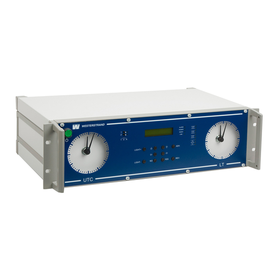
Document: 1717en19.doc MARINE MASTER CLOCK Author: PM Date: 2017-12-22 User Manual Page: 5 of 51 General description Westerstrand Marine Master Clock is the ideal solution for distribution of both Local and UTC time on board ships. The Master Clock is equipped with several outputs and inputs for control of Slave Clocks as well as distribution of time to computers and other equipment needing correct time. -
Page 9: Keyboard
Document: 1717en19.doc MARINE MASTER CLOCK Author: PM Date: 2017-12-22 User Manual Page: 6 of 51 Keyboard LIGHT+ Increase LED backlight level LIGHT- Decrease LED backlight level ↑ ↑ ↑ ↑ ↓ ↓ ↓ ↓ Select function / Change and scroll ←... -
Page 10: Installation
Document: 1717en19.doc MARINE MASTER CLOCK Author: PM Date: 2017-12-22 User Manual Page: 7 of 51 Installation The Marine Master Clock is intended for stand, cabinet, wall or desk mounting. Mount the Master Clock. Make sure that all analogue slave clocks shows the same time, for instance 12.00. Before connecting the slave clock lines, check the wires for short circuit, faulty connections etc. -
Page 11: Programming
Document: 1717en19.doc MARINE MASTER CLOCK Author: PM Date: 2017-12-22 User Manual Page: 8 of 51 Programming General Using 6 buttons and a 2-row 16-character display carries out all programming. Programming is self-instructive and to simplify the dialogue Yes/No questions are used. Running mode When the Time Base module is in operation it shows date MON 26 SEP 2016... -
Page 12: Start Up Procedure
Document: 1717en19.doc MARINE MASTER CLOCK Author: PM Date: 2017-12-22 User Manual Page: 9 of 51 Start up procedure 1. Start up questions (this page) 2. Output configuration / Setup (page 10) 3. Enter time of Slave Clocks (page 12) STARTING When the Master Clock is connected for the first time correct/requested LANGUAGE language has to be entered. -
Page 13: Output Configuration / Setup
Document: 1717en19.doc MARINE MASTER CLOCK Author: PM Date: 2017-12-22 User Manual Page: 10 of 51 Output configuration / Setup Each output can be individually configured regarding different parameters. The setup is done from the special function Setup. If the default setup is used no configuration is needed. Default setup: Slave Clock output no. -
Page 14: Set Utc When In Operation
Document: 1717en19.doc MARINE MASTER CLOCK Author: PM Date: 2017-12-22 User Manual Page: 11 of 51 Set UTC when in operation Select function using ↓. MON 26 SEP 2016 U10:11:35 L12:11 Enter the programming mode with YES. SET UTC Set, by using the arrows, the right UTC. SET UTC Time format: Year, month, date, hour, minute, second. -
Page 15: Slave Clock
Document: 1717en19.doc MARINE MASTER CLOCK Author: PM Date: 2017-12-22 User Manual Page: 12 of 51 Slave Clock Select function using ↓. MON 26 SEP 2016 U10:11:35 L12:11 Enter the programming mode with YES. SLAVE CLOCK IMPULSE OUTPUT 1 Select output using ↑↓. Accept with YES. IMPULSE OUTPUT 1 = 09.07? (Example) IMPULSE OUTPUT 1 If the slave clocks connected to impulse output 1 shows 09:07 answer YES,... -
Page 16: Time Zone Adjustment
Document: 1717en19.doc MARINE MASTER CLOCK Author: PM Date: 2017-12-22 User Manual Page: 13 of 51 Time zone adjustment To change Local Time zone two buttons are used. The buttons are named ADV and REV. To advance the Local Time slave clocks to a new time zone press button ADV. Example: MON 26 SEP 2016 Press button ADV. -
Page 17: Alarms
Document: 1717en19.doc MARINE MASTER CLOCK Author: PM Date: 2017-12-22 User Manual Page: 14 of 51 Alarms This function is used to display and erase the different alarms in the master clock. ALARMS- DISPLAY To show the alarms To erase the alarms ALARMS- ERASE Example 1, display alarms Select function using ↑↓... -
Page 18: Example 1, Erase Alarms
Document: 1717en19.doc MARINE MASTER CLOCK Author: PM Date: 2017-12-22 User Manual Page: 15 of 51 Example 1, erase alarms Select function using ↑↓ . MON 26 SEP 2016 U10:11:35 L12:11 ALARMS Accept with YES. Press NO until the wished function is shown. ALARMS- ERASE Accept with YES. -
Page 19: Alarm List
Document: 1717en19.doc MARINE MASTER CLOCK Author: PM Date: 2017-12-22 User Manual Page: 16 of 51 Alarm list The following alarms are available Type of alarm Indication Reason for alarm Action NO RADIO Red alarm LED lit. The Master Clock has Check the external General alarm relay activated. -
Page 20: Week Program & Date Program
Document: 1717en19.doc MARINE MASTER CLOCK Author: PM Date: 2017-12-22 User Manual Page: 17 of 51 Week Program & Date Program Using these two functions, programming of the outputs is made. Concept description Program "program" refers to programming an output to a certain time. The word program represents a single time event and several programs are defined as a group of programs. - Page 21 Document: 1717en19.doc MARINE MASTER CLOCK Author: PM Date: 2017-12-22 User Manual Page: 18 of 51 To simplify programming 3 sub menus are used: WEEK PROGRAM GROUP A To enter new programs. WEEK PROGRAM To erase a separate existing program. ERASE GROUP A WEEK PROGRAM To change existing programs.
-
Page 22: Week Program, Example 1 (New Program)
Document: 1717en19.doc MARINE MASTER CLOCK Author: PM Date: 2017-12-22 User Manual Page: 19 of 51 Week Program, example 1 (New program) Example: Outputs No. 2 shall switch on Monday – Friday at 09.00 and off at 17.00. 26 SEP 2016 Select function using ↑↓. -
Page 23: Week Program, Example 2 (Change Program)
Document: 1717en19.doc MARINE MASTER CLOCK Author: PM Date: 2017-12-22 User Manual Page: 20 of 51 Week Program, example 2 (Change program) Example: A signal on output 1, Monday – Friday at 08.00, shall be changed to 08.15. Signal length is 5 seconds. 26 SEP 2016 Select function using ↑↓... -
Page 24: Week Program, Example 3 (Erase Program)
Document: 1717en19.doc MARINE MASTER CLOCK Author: PM Date: 2017-12-22 User Manual Page: 21 of 51 Week Program, example 3 (Erase program) Example: A signal on output 1, Fridays at 16.30 shall be deleted. Signal length is 5 seconds. 26 SEP 2016 Select function using ↑↓... -
Page 25: Week Program, Example 4 (Astronomical Function)
Document: 1717en19.doc MARINE MASTER CLOCK Author: PM Date: 2017-12-22 User Manual Page: 22 of 51 Week Program, example 4 (Astronomical function) Example: Output No. 1 shall switch ON all sunset All days and switch OFF at sunrise. 26 SEP 2016 Select function using ↑↓... -
Page 26: Week Program, Example 5 (Block Program)
Document: 1717en19.doc MARINE MASTER CLOCK Author: PM Date: 2017-12-22 User Manual Page: 23 of 51 Week Program, example 5 (Block program) Example: Outputs No. 2 shall switch on Monday, Wednesday and Friday at 09.00. 26 SEP 2016 Select function using ↑↓ . U10:11:00 L12:11 WEEK PROGRAM Enter programming mode using YES. -
Page 27: Week Program, Example 6 (Mask Program)
Document: 1717en19.doc MARINE MASTER CLOCK Author: PM Date: 2017-12-22 User Manual Page: 24 of 51 Week Program, example 6 (Mask program) Example: Outputs No. 2 shall switch on for 5 seconds every hour at minute 15, all days in the week. 26 SEP 2016 Select function using ↑↓... -
Page 28: Date Program, Example (New Program)
Document: 1717en19.doc MARINE MASTER CLOCK Author: PM Date: 2017-12-22 User Manual Page: 25 of 51 Date Program, example (New program) Example: Outputs No. 1 shall switch on the 1st of August at 12.00. 26 SEP 2016 Select function using ↑↓ . U10:11:00 L12:11 DATE PROGRAM Enter programming mode using YES. -
Page 29: Display Program
Document: 1717en19.doc MARINE MASTER CLOCK Author: PM Date: 2017-12-22 User Manual Page: 26 of 51 Display Program 26 SEP 2016 Select function using ↑↓ . U10:11:00 L12:11 DISPLAY PROGRAM Enter display program using YES. DISPLAY PROGRAM Select program group using ↑↓, accept with YES. GROUP A Select output to be displayed using ↑↓, accept with YES. -
Page 30: Temporary Program, Example
Document: 1717en19.doc MARINE MASTER CLOCK Author: PM Date: 2017-12-22 User Manual Page: 27 of 51 Temporary Program, example Example: Outputs No. 2 shall switch on immediately 15.35.00 and turn off according to normal week program. The temporary program will automatically be erased when the event has been effected. 26 SEP 2016 Select function using ↑↓... -
Page 31: Group => Period
Document: 1717en19.doc MARINE MASTER CLOCK Author: PM Date: 2017-12-22 User Manual Page: 28 of 51 Group => Period Each program group can be associated to one or several time periods. A time period can consist of one or several dates. Maximum 99 time periods can be used. Program group A is as default associated to a time period covering the complete year, 1/1-31/12. -
Page 32: Spec.-Functions
Document: 1717en19.doc MARINE MASTER CLOCK Author: PM Date: 2017-12-22 User Manual Page: 29 of 51 Spec.-Functions The special functions contain functions used during setup and configuration of the Master Clock. If the default settings are used no configuration is needed. Select function using ↓... -
Page 33: Status
Document: 1717en19.doc MARINE MASTER CLOCK Author: PM Date: 2017-12-22 User Manual Page: 30 of 51 Status With this function each input/output status can be checked. Example: Check the status of the synchronisation source receiver. Select function using ↓ . MON 26 SEP 2016 U10:11:35 L12:11 Accept with YES. - Page 34 Document: 1717en19.doc MARINE MASTER CLOCK Author: PM Date: 2017-12-22 User Manual Page: 31 of 51 Status sync. source Type of synchronisation % of accepted messages NMEA RS485 60% 01 MAY 12:00:00 Last reception was 01MAY12:00:00*. *Remark: For W-GPS the marked position always shows the actual second. This information is updated every other second.
-
Page 35: Language
Document: 1717en19.doc MARINE MASTER CLOCK Author: PM Date: 2017-12-22 User Manual Page: 32 of 51 Language With this function the language be selected. Example: Select function using ↓ . MON 26 SEP 2016 U10:11:35 L12:11 Accept with YES. SPEC.-FUNCTIONS Press NO until wished function is shown. SPEC.-FUNCTIONS Accept with YES. -
Page 36: Setup
Document: 1717en19.doc MARINE MASTER CLOCK Author: PM Date: 2017-12-22 User Manual Page: 33 of 51 Setup With this function the different output and input can be configured. If the default setup is used no configuration is needed. Example: Set the alarm limit for synchronisation source alarm to 1 hour. (Default setting is 12 hours.) MON 26 SEP 2016 Select function using ↓... - Page 37 Document: 1717en19.doc MARINE MASTER CLOCK Author: PM Date: 2017-12-22 User Manual Page: 34 of 51 Setup sync. source Below is a description of the different configuration parameters available in the setup menu for sync. source. Please remark that if default settings are used no configuration is needed. Type of synchronisation NMEA RS485 AL.
- Page 38 Document: 1717en19.doc MARINE MASTER CLOCK Author: PM Date: 2017-12-22 User Manual Page: 35 of 51 Setup impulse output Below is a description of the different configuration parameters available in the setup menu for impulse output. Please remark that if default settings are used no configuration is needed. Impulse type Type of time Type of impulse...
- Page 39 Document: 1717en19.doc MARINE MASTER CLOCK Author: PM Date: 2017-12-22 User Manual Page: 36 of 51 Impulse length Configuration of impulse length. 1/1 and 1/2 -minute impulse: 0.1s – 9.9 s. Second impulses: 0.1 – 1.0 s. Alarm limits Impulse current low limit Impulse current high limit IL=0.0 - 2.0A UF= -- V...
- Page 40 Document: 1717en19.doc MARINE MASTER CLOCK Author: PM Date: 2017-12-22 User Manual Page: 37 of 51 Setup RS232 and RS485/422 output / input Below is a description of the different configuration parameters available in the setup menu for the RS232 and RS485 input/ output.
- Page 41 Document: 1717en19.doc MARINE MASTER CLOCK Author: PM Date: 2017-12-22 User Manual Page: 38 of 51 No. of stop bits, 1 or 2. Available formats: 7N1, 7N2, 7O1, 7O2, 7E1, 7E2, 8N1, 8N2, 8O1, 8O2, 8E1, 8E2, Protocol description ZDA - Time & Date - UTC, Day, Month, Year and Local Time Zone $--ZDA,hhmmss.ss,xx,xx,xxxx,xx,xx*hh<CR><LF>...
- Page 42 Document: 1717en19.doc MARINE MASTER CLOCK Author: PM Date: 2017-12-22 User Manual Page: 39 of 51 Protocol 2 The message has length 20 bytes according to: STX F G W 20 YY MM DD HH MM SS ETX BCC F - Flag bits =0 Winter time, =1 summer time =1 Synced from Radio source, e.g.
- Page 43 Document: 1717en19.doc MARINE MASTER CLOCK Author: PM Date: 2017-12-22 User Manual Page: 40 of 51 Protocol 3 At second 56 this message will be transmitted: HH:MM:00 SP DD/MN/YY SP NNN SP W CR LF (25 bytes) = Hour ‘00’ – ‘23’. = 3AH = Minute ’00’...
- Page 44 Document: 1717en19.doc MARINE MASTER CLOCK Author: PM Date: 2017-12-22 User Manual Page: 41 of 51 Protocol 7 STX WW VV YYYY MN DD HH MM SS F G BCC ETX (24 bytes) = 02h (1 byte). = Week number '01'-'53' = Weekday '01'-'07' YYYY = Year...
- Page 45 Document: 1717en19.doc MARINE MASTER CLOCK Author: PM Date: 2017-12-22 User Manual Page: 42 of 51 Protocol 16* STC HH MM SS DD MO MO YY HL HL ML ML ECT Code description Hex value Start Transmission Character 02 Ten UTC hours 30-32 Unit UTC hours 30-39...
- Page 46 Document: 1717en19.doc MARINE MASTER CLOCK Author: PM Date: 2017-12-22 User Manual Page: 43 of 51 Setup special pulse Relay output no. 2 can be dedicated to send out a special pulse. When this function is enabled the relay is activated every day for 5 seconds at 02.00 UTC. Use the procedure below to enable the special pulse.
- Page 47 Document: 1717en19.doc MARINE MASTER CLOCK Author: PM Date: 2017-12-22 User Manual Page: 44 of 51 Setup NMEA LT This function is valid only if the Master Clock is synchronised from an external NMEA source. Special function sync. source must be set to NMEA RS485 or NMEA RS232. With this function it can be selected if the Master Clock should use the Local Time (LT) information included in the NMEA time message.
-
Page 48: Software Version
Document: 1717en19.doc MARINE MASTER CLOCK Author: PM Date: 2017-12-22 User Manual Page: 45 of 51 SPEC.-FUNCTIONS ← SETUP SPEC.-FUNCTIONS ← MON 26 SEP 2016 U10:11:35 L12:11 Software version This function shows the software version for the Time Base module. Select function using ↓ . MON 26 SEP 2016 U10:11:35 L12:11 Accept with YES. -
Page 49: Default Lt Adjust
Document: 1717en19.doc MARINE MASTER CLOCK Author: PM Date: 2017-12-22 User Manual Page: 46 of 51 Default LT adjust This function is used to enter the default value used when pressing button ADV or REV. Example: Change default LT adj. from 60 minutes to 20 minutes. Select function using ↓... -
Page 50: Display Format
Document: 1717en19.doc MARINE MASTER CLOCK Author: PM Date: 2017-12-22 User Manual Page: 47 of 51 Display format With this function the display format in running mode can be selected. The following three formats can be selected: Format 1 MON 26 SEP 2016 LT = Local Time. -
Page 51: Programming Form
Document: 1717en19.doc MARINE MASTER CLOCK Author: PM Date: 2017-12-22 User Manual Page: 48 of 51 Programming form Function Group Output Type of Day/Date Time signal WESTERSTRAND URFABRIK AB P.O. Box 133 Tel. +46 506 48000 Internet:: http://www.westerstrand.se SE-545 23 TÖREBODA Fax. -
Page 52: Fault Tracing
Document: 1717en19.doc MARINE MASTER CLOCK Author: PM Date: 2017-12-22 User Manual Page: 49 of 51 Fault tracing The display is blank The green LED “POWER” is light? A1A. Check the supply voltage. A1B. Power supply wires connected correctly? Yes. A2A. Restart the master clock by switching the supply voltage off and on. -
Page 53: Alarm Output
Document: 1717en19.doc MARINE MASTER CLOCK Author: PM Date: 2017-12-22 User Manual Page: 50 of 51 “Exists” The signal point is already programmed. “Not programmed” When trying to change a non-existing signal point. Alarm output The Master Clock is equipped with two separate alarm relays. One relay for general alarm and one for power failure alarm. - Page 54 Document: 1717en19.doc MARINE MASTER CLOCK Author: PM Date: 2017-12-22 User Manual Page: 51 of 51 WESTERSTRAND URFABRIK AB P.O. Box 133 Tel. +46 506 48000 Internet:: http://www.westerstrand.se SE-545 23 TÖREBODA Fax. +46 506 48051 E-mail: info@westerstrand.se...
- Page 55 Document: 1785en03.doc INTELLIGENT CLOCKS Author.: TAn Date: 2009-11-04 Page: 1 of 5 WIRED DCF TIME CODE-CLOCK Max. 400 mm in diameter for Time zone adjustment TECHNICAL MANUAL WESTERSTRAND URFABRIK AB Box 133 Tel. 0506 48000 Internet: http://www.westerstrand.se 545 23 TÖREBODA Fax.
- Page 56 Document: 1785en03.doc INTELLIGENT CLOCKS Author.: TAn Date: 2009-11-04 Page: 2 of 5 General Westerstrand analogue clock for wired DCF Time-Code from Marine Master Clock provides the possibility to create a time distribution system, with high accuracy and high reliability. The clock is intended for connection to a 2-wire bus which combines power supply and serial Time-Code A built in microprocessor receives the Time Code, reads the position of the hands, and sets the clock to correct time.
- Page 57 Document: 1785en03.doc INTELLIGENT CLOCKS Author.: TAn Date: 2009-11-04 Page: 3 of 5 Technical data Art.no 113160-20,113160-22.113163-20,113163-22 Connection 2-wire Connection voltage 24VDC combined with serial Time-Code Type of time code DCF-format with Time zone adjustment. PIC16F628 Microcontroller Temperature range -20°C to +50°C Power consumption 20 mA.
- Page 58 Document: 1785en03.doc INTELLIGENT CLOCKS Author.: TAn Date: 2009-11-04 Page: 4 of 5 113160-20 113160-22 WESTERSTRAND URFABRIK AB Box 133 Tel. 0506 48000 Internet: http://www.westerstrand.se 545 23 TÖREBODA Fax. 0506 48051 E-mail: info@westerstrand.se...
- Page 59 Document: 1785en03.doc INTELLIGENT CLOCKS Author.: TAn Date: 2009-11-04 Page: 5 of 5 113163-20 M13x1 87.5 (17.5) 113163-22 WESTERSTRAND URFABRIK AB Box 133 Tel. 0506 48000 Internet: http://www.westerstrand.se 545 23 TÖREBODA Fax. 0506 48051 E-mail: info@westerstrand.se...
- Page 60 Document: 1795en03.doc WESTERSTRAND Author: PM Date: May 8, 2014 Page: 1 of 11 Option Ethernet Marine Master Clock WESTERSTRAND URFABRIK AB P.O. Box 133 Tel. +46 506 48000 Internet:: http://www.westerstrand.se SE-545 23 TÖREBODA Fax. +46 506 48051 E-mail: info@westerstrand.se...
- Page 61 Document: 1795en03.doc WESTERSTRAND Author: PM Date: May 8, 2014 Page: 2 of 11 List of contents List of contents ..............................2 General ................................3 Link indicator ..............................3 Technical data..............................3 Configuration...............................4 Status IP...............................5 Work mode (NTP Server or Client) .......................5 WEB browser ..............................6 Login window..............................6 Status >>................................7 General >>...............................8...
-
Page 62: General
Document: 1795en03.doc WESTERSTRAND Author: PM Date: May 8, 2014 Page: 3 of 11 General The Ethernet module makes it possible to connect a Master Clock to a LAN (Ethernet Local Area Network). The module can be built into a Marine Master Clock. The module can be used for Master Clock remote control, programming of relay outputs, alarm distribution, supervision and for distribution of correct time. -
Page 63: Configuration
Document: 1795en03.doc WESTERSTRAND Author: PM Date: May 8, 2014 Page: 4 of 11 Configuration Most of the configuration parameters are set via an external PC by using a Web-browser, but some of the settings can also be done from the Master Clock. The following parameters can be set from the Master Clock by using the special function setup. -
Page 64: Status Ip
Document: 1795en03.doc WESTERSTRAND Author: PM Date: May 8, 2014 Page: 5 of 11 Status IP Link- indicator Work mode Activity indicator 192.168.1.10 Present IP-address Work mode S = Server. The Master Clock works as a NTP time server. C = Client. The Master Clock works as a NTP time client. Link indicator L = Link activated. -
Page 65: Web Browser
Document: 1795en03.doc WESTERSTRAND Author: PM Date: May 8, 2014 Page: 6 of 11 WEB browser Login window The Web interface requires a password. Always use user name admin and a valid password. Default password is password. After login a function list is displayed.: WESTERSTRAND URFABRIK AB P.O. -
Page 66: Status
Document: 1795en03.doc WESTERSTRAND Author: PM Date: May 8, 2014 Page: 7 of 11 Status >> Displays the Master Clock status. The status is automatically updated every 10 second. WESTERSTRAND URFABRIK AB P.O. Box 133 Tel. +46 506 48000 Internet:: http://www.westerstrand.se SE-545 23 TÖREBODA Fax. -
Page 67: General
Document: 1795en03.doc WESTERSTRAND Author: PM Date: May 8, 2014 Page: 8 of 11 General >> To set general parameters. Name Symbolic name, maximum 48 characters Example: Station Master Clock. Password Enter a new password. The password has to be repeated. Firmware Function to enable firmware download. -
Page 68: Network
Document: 1795en03.doc WESTERSTRAND Author: PM Date: May 8, 2014 Page: 9 of 11 Network >> Used to set the network parameters. DHCP With this function it is defined if the Ethernet modules should receive its IP-address automatically from a DHCP server or use the static IP-address. -
Page 69: Ntp
Document: 1795en03.doc WESTERSTRAND Author: PM Date: May 8, 2014 Page: 10 of 11 NTP >> Used to set the NTP parameters. NTP mode NTP mode is set from the Master Clock keyboard, special function SETUP/SYNC SOURCE. See page 5. Server: The Ethernet module answers time request from clients. Client/Server: The Ethernet module acts as both a NTP client and a NTP server. -
Page 70: Help
Document: 1795en03.doc WESTERSTRAND Author: PM Date: May 8, 2014 Page: 11 of 11 Help>> Used to view a pdf help file. Technical remark When option Ethernet is mounted and synchronisation source NMEA RS485 is selected the RS485 output can only be used for transmission of NMEA ZDA time string with fixed baudrate (4800) and data format (8N1). WESTERSTRAND URFABRIK AB P.O. - Page 71 Document: 9539en14.doc WESTERSTRAND Author: PM Date: 2018-08-15 Page: 1 av 5 Technical specification Marine Master clock General The master clock has 6 buttons and one (2 line x 16 character) LCD. To facilitate time zone change there are 2 separate buttons for this purpose. The master clock also has a dimmer to adjust background illumina- tion.
- Page 72 Document: 9539en14.doc WESTERSTRAND Author: PM Date: 2018-08-15 Page: 2 av 5 Outputs for slave movements *: Control clocks: Analogue display, with background illumination. Output 1: Impulse system: 1/1 minute, 1/2 minute, second, 1/2 second, time code (TC) Type of time: LT, UTC Impulse length: Minute 0.1-9.9 sec.
- Page 73 Document: 9539en14.doc WESTERSTRAND Author: PM Date: 2018-08-15 Page: 3 av 5 Relay outputs Number of outputs: 2 Changeover potential-free contacts. Max load/relay output: 230 V 6A. Program memory: 100 year (EEPROM). Signal points: Special pulse output Relay output no. 2 can be dedicated to send out a special pulse. When this function is enabled the relay is activated every day for 5 seconds at 02.00 UTC.
- Page 74 Document: 9539en14.doc WESTERSTRAND Author: PM Date: 2018-08-15 Page: 4 av 5 Serial ports The Master Clock is equipped with two serial ports, one RS232 and one RS422/485. Both ports can be used either as input or output for serial time messages. If programmed as output the port can be used to send out time to external equipment such as computers etc.
- Page 75 Document: 9539en14.doc WESTERSTRAND Author: PM Date: 2018-08-15 Page: 5 av 5 Power supply The master clock has two inputs for power supply, one for AC, and one for 24V DC. As standard the DC-input is a direct connected input without galvanic isolation and no compensation for low input voltage. With option DC/DC the DC-input will be galvanic isolated and low / high input voltage is compensated automatically.
- Page 77 Calculation of Cable Area in Time Systems General To make a time system with impulse operated analog and digital slave clocks that performs satisfactorily, the cable from the Master Clock to the Slave Clocks needs to be dimensioned correctly. A 10% voltage drop is allowed in the cable. The length and area of the cable and the current (load) on the cable affect the voltage drop.
- Page 79 www.zenitel.com Zenitel Norway AS DOC NO. A100K10807 customer.service@zenitel.com Zenitel and its subsidiaries assume no responsibility for any errors that may appear in this publication, or for damages arising from the information therein. Vingtor-Stentofon products are developed and marketed by Zenitel. The company’s Quality Assurance System is certified to meet the requirements in NS-EN ISO 9001. Zenitel reserves the right to modify designs and alter specifications without notice. ZENITEL PROPRIETARY.
Need help?
Do you have a question about the MASTER CLOCK SYSTEM 70000 and is the answer not in the manual?
Questions and answers