
Related Manuals for TWERD Power Electronics MFC710 400V Series

Summary of Contents for TWERD Power Electronics MFC710 400V Series
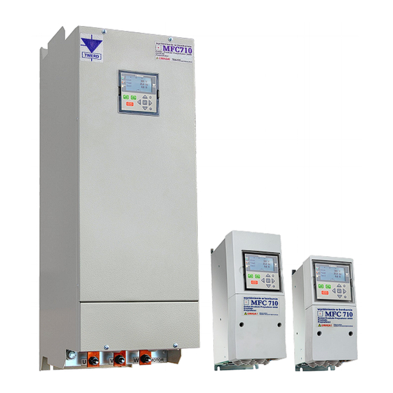
- Page 1 ® TWERD Power Electronics TWERD Vector controlled frequency converter MFC710 400V MFC710 500V MFC710 690V type with OP-11 control panel User Manual Edition 7.3 twerd www.
- Page 3 Vector controlled frequency converter MFC710 400V MFC710 500V MFC710 690V type with OP-11 control panel User Manual Edition 7.3...
-
Page 5: Table Of Contents
6.2.3. Remote deleting through RS link........................46 6.2.4. Readiness to restart if the reason of failure has not disappeared..............46 6.2.5. Automatic restarts............................47 6.3. Codes of failures and warnings..........................47 6.4. Failure and warning log............................49 Frequency converter MFC710 type. TWERD Power Electronics... - Page 6 GROUP 4 – PARAMETERS BLOCKING, CONFIGURATION OF: RS, DISPLAYING AND USER REFERENCING- UNITS.................................... 90 GROUP 5 – PUMP GROUP CONTROLLER, BLOCKS OF PLC CONTROLLER............92 GROUP 6 – PLC CONTROLLER – UNIVERSAL BLOCKS..................95 Appendix D – EU declaration of conformity........................96 Frequency converter MFC710 type with OP-11 control panel. TWERD Power Electronics...
-
Page 7: Technical Data
Additional functions of the Definition of User's referencing-device for direct changing of the process variables – panel selection of a unit of measurement and scale. Copying parameter settings between FC (frequency converters) Frequency converter MFC710 type with OP-11 control panel. TWERD Power Electronics... - Page 8 Underload Protection from operating without any load Stall Protection against the stall of a motor Table 0.2a – Technical data of frequency converters of the MFC710 400V series, depending on a type Constant-torque load Variable-torque load The type of frequency (max.
- Page 9 – nominal output power when the maximum overload current I is about 1.1 I (pumps, fans). – nominal output current at P – overload current: 60 seconds every 10 minutes. – maximum nominal current of the protection. Frequency converter MFC710 type with OP-11 control panel. TWERD Power Electronics...
-
Page 10: Installation Figures
The dimensions of frequency converter, type MFC710. Enclosure type A Enclosure type B Free space around the converter Ø1 Ø1 φ Ø2 Ø2 It is necessary to provide some free space around the converter for appropriate air circulation. Frequency converter MFC710 type. TWERD Power Electronics... - Page 11 7) Applies to converters from June 2022, previous weight is given in brackets. We also offer a frequency converters built in electric cabinets at different IP protection levels. The IP protection class is given in chapter 2.1.1.e. Frequency converter MFC710 type with OP-11 control panel. TWERD Power Electronics...
-
Page 12: Conditions Of Safe Operation
• The drive is not designed to operate with periodically switched on/off supply voltage. After turn off supply voltage wait 5 minutes before turn on it again. • If the electric motor runs at low speed (below 25 Hz), additional cooling of the motor is necessary. Frequency converter MFC710 type. TWERD Power Electronics... -
Page 13: Operation List
This way you help to prevent uncontrolled waste disposal and promote the recycling of materials. 1.6. Limits of responsibility Despite all the efforts and due diligence of TWERD Power Electronics does not guarantee that the published data is error-free. The User is obliged to read the information contained in this Manual before using the device. The TWERD Power Electronics Company is not responsible for any consequences of incorrect use of information contained in this Manual or any infringement of patents or other rights of third parties that may arise from their use. -
Page 14: Ce Marking
For technical reasons, in some applications (current > 400A or voltage 1000V ) fulfilling requirements of EMC is not possible. In such cases, a user and a manufacturer should decide on ways of satisfying EMC requirements in the particular application. Frequency converter MFC710 type. TWERD Power Electronics... -
Page 15: Installation Of The Frequency Converter
3G — yellow-green PE protective conductor (PE protective conductor is divided into 3 conductors — figure 2.2) *) Load capacity converted for ambient air temperature + 40 C (coefficient of 0.87). Frequency converter MFC710 type with OP-11 control panel. TWERD Power Electronics... -
Page 16: Safety Rules
• filtration. The basic way of connecting the filter, the frequency converter and the motor is presented in the figure 2.3. Fig. 2.3 - Connection of separate components of the electric drive system Frequency converter MFC710 type. TWERD Power Electronics... - Page 17 3) ferrite rings, 4) RFI filter (EPCOS, REO, SCHAFFNER), 5) EMC cabinet — optional, not required to comply with the EMC instructions. Fig. 2.5 - Installation principles reducing EMC problems Frequency converter MFC710 type with OP-11 control panel. TWERD Power Electronics...
-
Page 18: Connection Of Control Circuits
Uref = 10V - For use with analog inputs in voltage mode Fig. 2.6b - User terminal block and configuration switches of MFC710 converter. The control board variant for rated power 22 kW and above. Frequency converter MFC710 type. TWERD Power Electronics... - Page 19 For this reason, in order to avoid damage to the converter, it is necessary to control the OPERATING status of the converter (PCH.61), e.g. by using one of the relays. The default setting of the K2 relay (par. 2.92, 2.93) is suitable for this purpose. Frequency converter MFC710 type with OP-11 control panel. TWERD Power Electronics...
-
Page 20: Control Panel Op-11
Drive is in the blocking state – see chapter 4.4.3 Red „FAULT” Drive is in the failure state. After removing the cause of the failure, the drive will continue Yellow „READY” Flashing the work automatically. Frequency converter MFC710 type. TWERD Power Electronics... -
Page 21: Basic View
Refference-unit value = 0 Hz. (flashing) conventional direction of rotation Reference-unit via the RS "clockwise" Constant frequency < The converter works (Start) - (flashing) conventional direction of rotation Motopotentiometer "counterclockwise" Frequency converter MFC710 type with OP-11 control panel. TWERD Power Electronics... -
Page 22: Review And Change Of Parameters Values
0.79 AcR version 0.00 Changing parameters within the selected group 400 V Ulin 20.0 Hz fRef 0.0 A Imot Control panel with screen in "Basic view" Fig. 3.3 - Scheme of OP-11 control panel operation MFC710 User Manual - TWERD Power Electronics... -
Page 23: Changing Parameters Settings
400 V Ulin 01.03 Prad In 1.3 In 1.3 In 20.0 Hz fRef [ 0028.5] 12.0 30.0 Imot Canceling the changes made Fig. 3.4 - Graphic illustration of changing the parameter „1.3 In” MFC710 User Manual - TWERD Power Electronics... -
Page 24: Changing The Values Displayed In The Basic View
Note: After loading any set of factory settings, the converter is automatically restarted, during which communication with the keyboard is lost, and the following message appears on the display "Communication failure. Please wait...". MFC710 User Manual - TWERD Power Electronics... -
Page 25: Changing The Rotational Speed Of The Motor (Output Frequency) From The Control Panel
PD = 2 Note 2: After power off or reset of the converter (caused by e.g. loading of factory settings) the PD access level will automatically return to the PD 1 level. MFC710 User Manual - TWERD Power Electronics... -
Page 26: Parameters Locks
"4.3 New CODE". From now switching to the access level for which the code has been changed will take place after entering this new code in par. "4.2 Level/CODE". Access level 0 has no code. MFC710 User Manual - TWERD Power Electronics... -
Page 27: Configuration Of The Frequency Converter
Control place B START / - PID-regulator with RS Choice of a control STOP - Another sources source Par. 2.3 (Ref.-unit) Par. 2.5 (START) Par. 2.1 Fig. 4.2a – The control structure simple diagram MFC710 User Manual - TWERD Power Electronics... - Page 28 Configuration of Sel.A0 Par. 2.43, 2.46 PCH.144 MFC710 (scale and offset) Signal «Blocking of electro drive». Structure of frequency selector When frequency is low par. 2.13 Configuration of PCH.145 and par. 2.14 = TAK (YES) Sel.A1 Par. 2.44, 2.47 (scale and offset) Min.
- Page 29 MFC710 Structure of control START / STOP LOCAL REVERSE (PCH.34) START / REVERSE A PANEL LOCAL START Par. 2.4 A / B ERASE OF LOCAL PCH.31 (PCH.39) START No RS constraint par. 2.1 BLOCKING Par. 2.xx - If fault has done REMORE START OPERATION - Electric drive operates low F STOP (par.
-
Page 30: Control From The Control Panel
Note: Digital input DI3 is default using as a source of external fail 1 (par. 3.10 = In.C3), so before using DI3 to change direction please move a source of external fail 1 to another digital input DI or just turn it off. Frequency converter MFC710 type. TWERD Power Electronics... -
Page 31: Work With Constant Speeds
When constant speed referencing-unit is active display looks like it is shown in fig. 4.5. Fc – Referencing-unit: constant frequency (speed), Di – START through digital input. 400 V Ulin 20.0 Hz fRef 0.0 A Imot Fig.4.5 - CONTROL STATE Frequency converter MFC710 type. TWERD Power Electronics... -
Page 32: Motopotentiometer
Referencing frequency from an output of the PID controller (see section 8), Advanced functionalities related to the use of built-in PLC or a control system of group of pumps (see section 10 and the following sections). Frequency converter MFC710 type. TWERD Power Electronics... -
Page 33: Configuration Of Digital And Analog Inputs And Outputs
In operating modes 2..10V, 10..2V, 4..20mA and 20..4mA it is possible to define behavior of the 3.23 absence at the Analog drive when value of voltage falls below 1V or value of a current falls below 2mA (see Input Appendix C - par. 3.23). Frequency converter MFC710 type. TWERD Power Electronics... - Page 34 0-20mA (4-20mA). The choice of an operating mode is carried out by switches J1 and J2 (see fig. 2.6). Note: Analog outputs in voltage mode should be loaded by impedance in value not less then 10kOm. Frequency converter MFC710 type. TWERD Power Electronics...
- Page 35 Value of analog output 1 Out.А1 = Absolute value (signal * AO1 scale / 1000) Out.A2 0...100.0% READ ONLY. 0.44 Value of analog output 2 Out.А2 = Absolute value (signal * AO2 scale / 1000) Frequency converter MFC710 type. TWERD Power Electronics...
-
Page 36: Configuration Of The Drive
Mode U/f exponential. It is used if the torque of loading grows under the exponential from speed (e.g. the drive of the fan). Use of exponential characteristic U/f cause reduction of noise and decrease of losses in the motor. Fig. 4.11 - Linear and exponential characteristic(a), formation of U/f characteristic (b) Frequency converter MFC710 type. TWERD Power Electronics... -
Page 37: Elimination Of Frequencies
Below this speed a command to close the mechanical brake is sent. [rpm] 2.103 Br. close t. Time of work after closing command is sent [s] – time needed for complete locking of mechanical brake. Frequency converter MFC710 type. TWERD Power Electronics... -
Page 38: Flying Start
Blocking from „F STOP”: There is a built-in blockade in referencing-unit structure. It is switched on by parameter 2.14. If it is set on "No" par. 2.13 determines the minimal frequency value, below which frequency will not decrease (by Frequency converter MFC710 type. TWERD Power Electronics... -
Page 39: Thermal Protections Of The Motor
0.9 100% f [Hz] 25 Hz Time Constant of heating time, par. 3.5 Fig. 4.17 - Definition of area of long operation (a), Dependence of calculated temperature from motor's current (b) and (c) Frequency converter MFC710 type. TWERD Power Electronics... - Page 40 Thermal relay (PTC) in electric in electric motor motor Terminal Terminal control block of block of control MFC710 MFC710 R[kОhm] time Failure 24 Fig.4.19 – Thermal protection by thermorelay (a) or thermistor (b) Frequency converter MFC710 type. TWERD Power Electronics...
-
Page 41: Autostart Blockade
2.18 = 1 Power on START signal, e.g. from Working Autostart blockade inactive par. 2.18 = 0 Power on START signal, e.g. from Working Fig. 4.20 – Autostart lock function Frequency converter MFC710 type. TWERD Power Electronics... -
Page 42: Motor Drying Function
The state of the motor drying process can be read in register 2007, bit 1 - see chapter 13.2 Map of registers available through the RS interface. The address of the Description (meaning) Mode registers (decimal) 2007 bit 1 = 1 - the motor drying process is in progress Read only Frequency converter MFC710 type. TWERD Power Electronics... - Page 43 1.97 = 20.0%, par. 1.98 = 5.0%, par. 1.99 = 200.0 h. Note: Using the motor drying function without monitoring the temperature of the motor windings may overheat these windings and damage the motor. Frequency converter MFC710 type. TWERD Power Electronics...
-
Page 44: The First Start
EEPROM memory of the frequency converter (fig. 5.1e). Then STOP button should be pressed to restart the converter. It is possible to interrupt procedure of testing in the same way at any time. At the end the vector mode is set using parameter 1.20: Vector1 or Vector2. Frequency converter MFC710 type. TWERD Power Electronics... -
Page 45: Storing And Reading Of Options For 4 Different Motors
(from 1 up to 4) in which parameters have been stored and to confirm reading. Reading empty buffer or buffer "0" will not result in changing current parameters. ATTENTION. Procedure of record / reading can be made only when the motor is stopped. Frequency converter MFC710 type. TWERD Power Electronics... -
Page 46: Failures And Warnings
400 V Ulin 20.0 Hz fRef 0.0 A Imot Yellow led is blinking Fig. 6.3 - Ready to restart When the reason of failure will disappear, automatic restart of the drive will begin. Frequency converter MFC710 type. TWERD Power Electronics... -
Page 47: Automatic Restarts
The current of the motor is to Too high intensity of acceleration, a Increase acceleration time of the High current high sudden change of motor loading motor Frequency converter MFC710 type. TWERD Power Electronics... - Page 48 (F/W – RS time the transmission are incorrectly set RS is exceeded validity of RS parameters par. 3.60) Voltage oscillations of circuit U mains Voltage oscillation of power source DC are higher than allowable Frequency converter MFC710 type. TWERD Power Electronics...
-
Page 49: Failure And Warning Log
Time 95 h failure Incident code Incident name Frequency converter working hour at which the incident occurred Incident type: Fault or Warning Fig. 6.5 – Failure register - example of the newest record Frequency converter MFC710 type. TWERD Power Electronics... -
Page 50: Sets Of Factory Parameters
Par. 0.7 Par. 0.20 Par. 0.7 Par. 0.7 Par. 0.7 Par. 0.7 Par. 0.7 Ref.A0 Ref.A0 Ref.A0 Ref.A0 Ref.A0 Ref.A0 Ref.A0 Ref.A0 Ref.A0 5.10 5.27 Ref.A0 Ref.A0 Ref.A0 Ref.A0 Ref.A0 Ref.A0 Ref.A0 RefPID Ref.A0 Frequency converter MFC710 type. TWERD Power Electronics... -
Page 51: Pid Controller
Current value of PID controller input. READ ONLY 0.32 PID error Value of current regulator error par 0.32 = par 0.30 – par 0.31 READ ONLY 0.33 OutPID Current value of PID controller output. READ ONLY Frequency converter MFC710 type. TWERD Power Electronics... -
Page 52: Limitation Of Saturation And Sleep Function
For determining current diameter of a roller there is necessary an information about linear speed of rolled medium. In presented example linear speed signal is obtained from frequency converter which cooperates simultaneously in production line. Frequency converter MFC710 type. TWERD Power Electronics... -
Page 53: Turning On And Configuration Of Rc
The frequency converter decides which of pumps is the leading one and also automatically replaces the leading pump and turns on/shuts down additional pumps. L1 L2 MFC710 PUMP 1 PUMP 2 PUMP 3 Fig. 10.1 – Power circuit of 3 pumps group Frequency converter MFC710 type. TWERD Power Electronics... -
Page 54: Parameters Of A Pump Group Controller
- par. 2.66 and 2.67 should be set up on values 100% and 0 % respectively. Simpler way of setting up parameters is loading of factory parameters, set number 8 which is especially prepared for a pump group controller group, with subsequent changing only some options. Frequency converter MFC710 type. TWERD Power Electronics... -
Page 55: An Operating Mode With The Pid Controller And A Mode Of Direct Control
Leading pump: Pump Control is switched off Pump 1 Fig. 10.3 – Information about state of the Control system of pumps group Fig. 10.4 – Information about pumps by means of par. 0.34 state Frequency converter MFC710 type. TWERD Power Electronics... -
Page 56: Conditions Of Switching On/Off Additional Pump
Condition: the maximum quantity of pumps is set up on 5, all pumps are not blocked. Example 2: If pumps P2 P4 are blocked and the main pump is P1 in this case switching on sequence is following: P3 → P5 switching off sequence: P5 → P3 Frequency converter MFC710 type. TWERD Power Electronics... -
Page 57: Automatic Replacement Of Pumps
(according to a sequence from fig. 9.6a) main pump provided that it is not blocked and can operate from the frequency converter. By temporarily blocking of main pump operation you can force replacement (accelerated) of this pump. Frequency converter MFC710 type. TWERD Power Electronics... -
Page 58: Advanced Programming Of Mfc710
1. Unblock possibility of parameters changing (see a way in section 3.9), 2. Set Parameter 4.6 on value "001 YES", 3. Change appropriate parameter of the frequency converter (the ) 4. If it is necessary block possibility of parameters changing. Frequency converter MFC710 type. TWERD Power Electronics... -
Page 59: The Control Panel - Defining Displayed Values
UR1), 2 (for UR2), 3 (for UR3) or 4 (for UR4). Value defines choice of the measurement unit is set up on active referencing-unit. In fig. 11.5 change of the Referencing-unit for "item" par 4.30 = 1 is shown. Frequency converter MFC710 type. TWERD Power Electronics... -
Page 60: System Of Rotation Counter
Counter counts „up” or „down” in range -32000 ... 32000. Current value of counter is placed in PCH.177. System of rotations counter used in structure of PLC control can serve, for example, to set programmed quantity of rotations of drive's shaft. Frequency converter MFC710 type. TWERD Power Electronics... -
Page 61: Plc Controller
NOTE 1. Units with numbers higher than par. 5.145 are not executed! NOTE 2. The sequencer device, Multiplexers and Curve shaping unit should be placed in one of the function blocks to activate them. Frequency converter MFC710 type. TWERD Power Electronics... -
Page 62: Sequencer Device
1 (the most high priority) up to 48 (see the description of a sequencer operation - Fig. 12.4 - Multiplexers MUX1 and MUX2 section 12.2). As in sequencer most parameters (inputs) are pointers. They are presented in fig. 12.4. Frequency converter MFC710 type. TWERD Power Electronics... -
Page 63: Curve Shaping Unit
X * 5, that in our case corresponds to value of an analog input 0 increased 5 times, which means it changes in limits from 0 to 5000 (0.0...500.0 %) (fig. 12.6). Frequency converter MFC710 type. TWERD Power Electronics... -
Page 64: Example Of Plc Use
100.0 %], the parameter 5.121 will define a threshold of speed N2 [resolution 0.1 %, that is 1000 = 100.0 %], a parameter 5.122 time T with resolution of one second. Fig. 12.8 - Structure of control implementing a predefined task Frequency converter MFC710 type. TWERD Power Electronics... -
Page 65: Control Of The Frequency Converter By Means Of Connection Rs
5. Forcing of control with RS by means of bits 4,5,6 results in switching off a source of the control established with parameters. Bits 12,13,14 block operation of the drive irrespective of the established type of control (also when, for example, there is control through RS and bits 15 = 1). Frequency converter MFC710 type. TWERD Power Electronics... - Page 66 Details: section 3.2 and following. Parameters from group 2. They are similar with parameters on the control panel, e.g. the register 42001 corresponds to parameter 2.1. 42xxx Read / write CAUTION: the same as item 41xxx. Frequency converter MFC710 type. TWERD Power Electronics...
-
Page 67: Handling Of Connection Errors
The manufacturer is not responsible liability for defects caused by transport, improper use, faulty installation, inappropriate environmental conditions (e.g. temperature, humidity, presence of corrosive agents) and as a result of exceeding rated parameters. Frequency converter MFC710 type. TWERD Power Electronics... -
Page 68: Appendix A - Table Of Characteristic Points
H when referencing-unit of constant frequency is switched on. Depends from PCH, defined in Fconst is active the parameters 2.30,2.31,2.32. 043...058 Reserve. Value = always 0 PUMP 6 Pump system control. H = pump 6 operates K_ZERO Value = always 0 OPERATION H when drive operates Frequency converter MFC710 type. TWERD Power Electronics... - Page 69 Value of analog input 0 multiplied by parameter of scale 2.43 and added offset – parameter 2.46 Value A1 Value of analog input 0 multiplied by parameter of scale 2.44 and added offset – parameter 2.47 Frequency converter MFC710 type with OP-11 control panel. TWERD Power Electronics...
- Page 70 Lrot Value of rotation counter. Value of the user referencing-unit number 1. Value of the user referencing-unit number 2. Value of the user referencing-unit number 3. Value of the user referencing-unit number 4. Frequency converter MFC710 type. TWERD Power Electronics...
- Page 71 PLC controller. Sequencer system. Value H = active mode 1 (only one of the PCH.304...311 can STATE 1 assume value H at the same time and only if the sequencer is switched on) Frequency converter MFC710 type with OP-11 control panel. TWERD Power Electronics...
- Page 72 PCH accessible for writing using a connection RS. There is a possibility of an external control of 384...447 PCH RS 1...64 a process which takes values from these PCH PCH intended for service by means of optional extension module (additional inputs/outputs – 448...511 PCH EXT 1...64 analog, digital, etc.) Frequency converter MFC710 type. TWERD Power Electronics...
-
Page 73: Appendix B - Table Of Functions Of Universal Blocks
(a - B)*1000 / (C - B) Graduation. The input value a will be transformed from a range determined by parameters B and C to a range 0...1000 (0.0...100.0 % 1000 Frequency converter MFC710 type with OP-11 control panel. TWERD Power Electronics... - Page 74 Current value of the “One shot” counter type, counting down with an input setting on initial value (SET) and an counter: input of initial value. a = CLK, b = SET, c = initial value Frequency converter MFC710 type. TWERD Power Electronics...
- Page 75 = switching on impulse (leading edge) b = switching off impulse (leading edge) C = delay on shut down *T = par 5.145 x 0.2 ms Frequency converter MFC710 type with OP-11 control panel. TWERD Power Electronics...
- Page 76 The value from PCH number “c” is writing by CAN to “A” drive, “B” address – see A – drive number tab. 13.2. B – register address c – PCH Note: reading can be done only by master drive (drive number = 0) Frequency converter MFC710 type. TWERD Power Electronics...
-
Page 77: Appendix C - Table Of Mfc710 Frequency Converter's Parameters
Value of the analog referencing-unit 0 [%] 0.46 Ref. A1 Value of the analog referencing-unit 1 [%] 0.47 Ref. A2 Value of the analog referencing-unit 2 [%] 1) Parameter is available from software version 12.63 Frequency converter MFC710 type with OP-11 control panel. TWERD Power Electronics... -
Page 78: Group 1 - Configuration Of The Drive
1.14 Ls Stator inductance Ls 0.0 ... 3200.0 0.0 mH 1.15 Lr Rotor inductance Lr 0.0 ... 3200.0 0.0 mH 1) The number of decimal places depends on the nominal power of frequency converter Frequency converter MFC710 type. TWERD Power Electronics... - Page 79 Torque limitation at motor 0.0 ... 180.0 % motor Mn 150.0 % operation 1.44 T limit G Torque limitation at 0.0 ... 180.0 % motor Mn 150.0 % generator operation Frequency converter MFC710 type with OP-11 control panel. TWERD Power Electronics...
- Page 80 000 Sw.Off – disabled 001 In.C1… 006 In.C6 – enabled when voltage is applied to digital input 1 ... 6 007 Sw.On - enabled 1.70 Amp. reg.n Speed regulator gain Service parameter for Vector modes Frequency converter MFC710 type. TWERD Power Electronics...
- Page 81 200.0 h to 0 h, but after it reach the 0 h, the drying process will still going on. 1) Параметр доступен c версией программного обеспечения 12.63 Frequency converter MFC710 type with OP-11 control panel. TWERD Power Electronics...
-
Page 82: Group 2 - Referencing-Units And Control
032 RS St. – START/STOP control through RS232 or RS485 (Modbus) 2.5 Start B Choice of a source of as above 030 Dig.In START / STOP signal for Control B Frequency converter MFC710 type. TWERD Power Electronics... - Page 83 Source of “decrease” 000 Sw.Off – disabled 000 Sw.Off signal for 001 In.C1 … 006 In.C6 – decrease ref.-unit, when motopotentiometer ref.-unit there is a voltage supplied on digital input DI1...DI6 Frequency converter MFC710 type with OP-11 control panel. TWERD Power Electronics...
- Page 84 Configuration of analog as above 0-10 V input AI2 2.43 In.A0 Scale Scale of analog -500.0 ... 500.0 % 100.0% referencing-unit RefA0 2.44 In.A1 Scale Scale of analog -500.0 ... 500.0 % 100.0% referencing-unit RefA1 Frequency converter MFC710 type. TWERD Power Electronics...
- Page 85 2.71 SLEEP thr A threshold of "wakening" 0.0 ... 100.0 % 5.0 % from SLEEP state Waking up when: (Error > par 2.71) or (PID output > par 2.71) Frequency converter MFC710 type with OP-11 control panel. TWERD Power Electronics...
- Page 86 2.86 Out.A1 Fltr Constant of time of 0.10 s lowpass filter AO1 100% 0.01 ... 50.00 s Par. 2.86 2.87 Out.A2 Fltr Constant of time of as above 0.10 s lowpass filter AO2 Frequency converter MFC710 type. TWERD Power Electronics...
-
Page 87: Group 3 - Failures
Switching on blocking from 000 NO – disabled 001 YES thermal overload 001 YES – enabled 3.3 I therm. Setting of motor thermal 0.0 ... 200.0 % 100.0 % protection current Frequency converter MFC710 type with OP-11 control panel. TWERD Power Electronics... - Page 88 3.50 Re. Underl. Reaction to underload 000 None – no reaction 000 None 001 Warning – a warning will be displayed 002 Failure – device will stop and message will be displayed Frequency converter MFC710 type. TWERD Power Electronics...
- Page 89 Read only occurrence of failure from Failure Register 1 … … … … … 3.110 Failure 16 Failure Register 1 (the Failure name (read only) Read only oldest record) Frequency converter MFC710 type with OP-11 control panel. TWERD Power Electronics...
-
Page 90: Group 4 - Parameters Blocking, Configuration Of: Rs, Displaying And User Referencing-Units
OP-11 control panels - they do not have possibility of contrast adjustment. 4.22 RTC set. RTC setting Option – requires additional RTC module 1: year 2: month 3: day of month 4: day of week 5: hour 6: minute Frequency converter MFC710 type. TWERD Power Electronics... - Page 91 Displayed unit of par. 0.57 (Usr4). See table 11.3 005 % 4.71 Usr4 dec.p. Number of decimal places Number of decimal places for par. 0.57 (Usr4): 0 ... 3 1 Frequency converter MFC710 type with OP-11 control panel. TWERD Power Electronics...
-
Page 92: Group 5 - Pump Group Controller, Blocks Of Plc Controller
5.17 P2 active Pump 2 activation 000 Sw.Off – pump disabled 002 In.C2 001 In.C1 … 006 In.C6 – pump enabled by one of digital inputs DI1 … DI6 007 Sw.On – pump enabled Frequency converter MFC710 type. TWERD Power Electronics... - Page 93 5.49 Seq time 7 Time of 7th state duration PCH.000 Sw.Off ... PCH.511 PCH.326 Constant.7 5.50 Seq time 8 Time of 8th state duration PCH.000 Sw.Off ... PCH.511 PCH.327 Constant.8 Frequency converter MFC710 type with OP-11 control panel. TWERD Power Electronics...
- Page 94 -32000 ... 32000 5.109 CSU Y4 Point 4, value Y -32000 ... 32000 5.110 CSU X5 Point 5, value X -32000 ... 32000 5.111 CSU Y5 Point 5, value Y -32000 ... 32000 Frequency converter MFC710 type. TWERD Power Electronics...
-
Page 95: Group 6 - Plc Controller - Universal Blocks
6.192 Inp. C. 48 Input C of block 48 PCH.0 ... PCH.511 Parameter is accessible or not, PCH.000 depending on function of block (par 6.189) Sw.Off dtr_mfc710_OP11_en_e7.3_22-08 : 2022/08/09 Frequency converter MFC710 type with OP-11 control panel. TWERD Power Electronics... -
Page 96: Appendix D - Eu Declaration Of Conformity
Appendix D – EU declaration of conformity Appendix D – EU declaration of conformity Frequency converter MFC710 type. TWERD Power Electronics... - Page 98 Zakład Energoelektroniki TWERD sp. z o.o. ul. Aleksandrowska 28-30 87-100 Toruń, Poland tel. +48 56 654-60-91 e-mail: twerd@twerd.pl SCALONE FIGURY twerd www.
Need help?
Do you have a question about the MFC710 400V Series and is the answer not in the manual?
Questions and answers