Advertisement
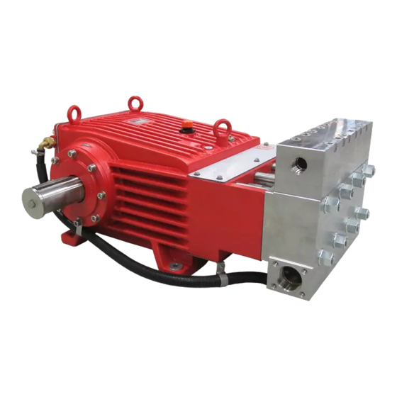
Repair Instructions - GP8035 Pump
To Check Valves
Loosen screws (58) and lift discharge casing (50B) up and away. Take out pressure springs
(57). Pull out assembled valves (51 and 52) with fi tting tool (p/n 07662).
Dismantling valves: the spring tension cap (51A, 52A) is screwed together with the valve
seat (51B/52B). Remove spring tension cap, take out springs (51E/52E) and valve plate
(51C/52C). Check sealing surfaces and O-rings (51D/F, 52D/F, 56A).
Replace worn parts.
Coat threads of valve seat with silicon grease or molycote anti-seize Cu-7439 when reas-
sembling. Before refi tting the valves, clean the sealing surfaces in the casing and check for
any damage.
Tighten screws (58) at 132 Ft-lbs (180 NM); check torque tension after 8-10 operating
hours.
To Check Seals and Plunger Pipe
Screw off hexagon nuts (49A) and hose coupling (K11 and K15). Remove pump head
together with seal case (38) and intermediate casing (62) from crankcase (1). If necessary,
carefully tap the valve casing (50) past the centering stud (50A) using a rubber hammer.
Important! If necessary, support the pump head by resting it on wooden blocks or by using
a pulley.
Take off fl at leakage seal (62D) and check.
Remove plunger (36) from crosshead with plunger base (25) and take seal sleeve (39)
together with all mounted parts out of the drive.
Pull plunger out of seal assembly and check for any damage. Clean centering and top-sur-
face of crosshead with plunger base (25). Take out tension spring (45). Carefully remove
the whole seal unit (41-44) by using socket wrench or backside of a screwdriver. Check
plunger surface and seals. Check O-rings (39A).
Renew damaged parts.
After removing off clip-ring (40C) and pressure ring (40B), check leakage seal (40) and O-
ring (40A) and renew (if necessary).
Important! Be careful not to damage seal sleeve (39) pressure ring (41) and guide ring
(41A). Check the inner diameter of the pressure ring and guide ring for wear and if nec-
essary replace together with seals (42) and support ring (44). Clean all parts. New parts
should be lightly coated with silicon grease before installation.
Insert the seal unit (41-45) into the seal sleeve (39). Push the plunger (36) carefully
through the seals from the crankcase side. If necessary, the seals can be held tightly using
a suitable pipe support held on the other side of the seal sleeve.
Take out the seal case (38) from the intermediate casing (62) and check O-rings (38A). If
necessary, secure 2 screwdrivers in the front O-ring groove to extract seal casing from
intermediate casing. Coat O-rings with silicon grease before installing.
Important! Mounting surfaces of the crankcase, seal sleeves, intermediate casing and
7
Advertisement
Table of Contents

Related Manuals for GIANT PUMPS GP8035


Summary of Contents for GIANT PUMPS GP8035
- Page 1 Repair Instructions - GP8035 Pump To Check Valves Loosen screws (58) and lift discharge casing (50B) up and away. Take out pressure springs (57). Pull out assembled valves (51 and 52) with fi tting tool (p/n 07662). Dismantling valves: the spring tension cap (51A, 52A) is screwed together with the valve seat (51B/52B).
- Page 2 Repair Instructions - GP8035 Pump valve casing must be clean and free of damage. The components must lie exactly and evenly on one another. The same exactness applies for all centering positions in the crank- case, intermediate casing, pressure-and valve casing.
- Page 3 Repair Instructions - GP8035 Pump To Dismantle Crankcase Gear 11) Remove the connecting rod 10) Take out plungers and seal sleeves as screws (24). described above. Drain the oil by taking off the plug (12). After removing the clip ring...
- Page 4 Repair Instructions - GP8035 Pump 14) Mount bearing cover (14A) and tighten screws (17) to 64 Ft-lbs. Adjust axial play (clear- ance) on the crankshaft to minimum 0.1 mm / max. 0.15 mm using shims (21A/21B). The shaft should turn easily with little clearance. Connecting rod must sit exactly in the middle of each crank pin.
Need help?
Do you have a question about the GP8035 and is the answer not in the manual?
Questions and answers