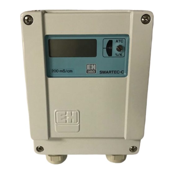
Summary of Contents for Smartec CLD 130
- Page 1 BA 001C/07/en/02.97 smartec No. 50040314 CLD 130 Conductivity Measurement Operating Instructions Quality made by Endress+Hauser ISO 9001...
-
Page 2: Table Of Contents
Table of contents Smartec CLD 130 BE1LD130.CHP Table of contents General ............2 – 3 Unpacking . -
Page 3: General
General Smartec CLD 130 General Unpacking Application • Inspect for any damaged packaging! Use: Conductivity measurement The post office or forwarding agent must be informed of any damage. Measuring Damaged packaging material must be principle: inductive retained until the matter has been settled. -
Page 4: Order Code
General Smartec CLD 130 BE1LD130.CHP Order code Inductive instrument Smartec CLD 130 Design P Compact design with in situ measuring transmitter / PEEK W Separate measuring transmitter with 5 m cable / PEEK X Separate measuring transmitter with special cable length (max. 15 m) / PEEK... -
Page 5: Measuring System
+ 130 °C. to the second coil T proportional to the Therefore, Smartec can be sterilized. conductance G of the test medium. This yields a linear relationship between the The sensor is available in different mounting... -
Page 6: Designs
Measuring system Smartec CLD 130 BE1LD130.CHP Designs 2.4.1 Sensor with integrated 2.4.3 Immersion sensor with transmitter integrated transmitter The sensor with integrated measuring The measuring system comprises: transmitter including screw connection, Measuring transmitter with immersion pipe, provides a complete measuring unit. -
Page 7: Installation
Installation Smartec CLD 130 Installation Sensor with integrated transmitter The Smartec measuring system is available in The version with integrated measuring different designs for all commonly used transmitter is suitable for use with continuous mounting and installation versions for medium temperatures of up to 90 °C and industrial applications: ambient temperatures of up to 50 °C. -
Page 8: Sensor With Separate Transmitter
Installation Smartec CLD 130 BE1LD130.CHP Sensor with separate transmitter Smartec with a separate measuring The measuring transmitter is then mounted transmitter is available for industrial separately and connected to the sensor via a applications with high permanent 5 metres long double shielded double coaxial temperatures (>90 °C) and hardly accessible... -
Page 9: Sensor With Integrated Transmitter
Immersion sensor with separate transmitter For installation in tanks or other closed ∅ 47 containers, Smartec CLD 130 is available as an immersion assembly with a separate measuring transmitter. The inductive sensor is mounted in the Fig. 3.4: Immersion sensor with assembly using a bayonet lock. -
Page 10: Separate Transmitter
Installation Smartec CLD 130 BE1LD130.CHP Exchanging of the sensor 1. Unscrew Pg thread of cable duct on top of the assembly (see fig. 3.5, or ). 2. Loosen sensor by turning it anticlockwise (bayonet lock 3. Withdraw the sensor part with protection... -
Page 11: Electrical Connection
However, this is only valid for a (24 V AC version) properly grounded instrument with Smartec CLD 130 can be operated in the a screened measured value output direct voltage mains by inserting of a DC/AC line. -
Page 12: Sensor With Separate Transmitter
Electrical connection Smartec CLD 130 BE1LD130.CHP Sensor with separate transmitter Inductive Sensor Pt 100 Measuring cable Measuring transmitter Pt 100 κ Ι KL1(A) – – 0/4-20mA Power supply 24 V to 240 V AC (see nameplate) Fig. 4.2: Connection diagram for... -
Page 13: Start-Up
Start-up Smartec CLD 130 Start-up Power-up ATC setting Before switching on, ensure that all The automatic temperature compensation connections have been correctly made (ATC) factor can be set externally on the according to chapter 4. scaled ATC control (see chapter 6.2). If the factor is not known refer to chapter 6.2. -
Page 14: Operation
Pt 100 S101 Terminal 1 signal output Terminal 2 Power supply Control R110 Control R107 end of range start of range Fig. 6.2: Inside view Smartec CLD 130 - componentry with terminals and plugs for measuring range change-over... -
Page 15: Atc Adjustment (Automatical Temperature Compensation)
Operation Smartec CLD130 6.2 ATC adjustment (automatical temperature compensation) • If the temperature coefficient is known it is The actual temperature coefficient for the set on the scaled ATC control on the front medium used is now indicated on the ATC panel using a screwdriver. -
Page 16: Signal Output Change-Over
Operation Smartec CLD 130 BE2LD130.CHP 6.3 Signal output change-over Switch S 101 Output range The signal output can be switched to 0 ... 20 mA or 4 ... 20 mA using switch S 101 0 ... 20 mA – –... -
Page 17: Remote Switching Of Current Output
Selected measuring range Table 6.3: Measuring range Selected measuringrange assignment for remote switching Terminal 1 A signal output Terminal 1 B remote switching Fig. 6.5: Inside view of Smartec CLD 130 - remote switching connection... -
Page 18: Maintenance And Troubleshooting
7. Maintenance and troubleshooting Smartec CLD 130 BE2LD130.CHP 7. Maintenance and troubleshooting 7.1 Maintenance Measuring transmitter and sensor are maintenance-free. No parts wear out. 7.2 Troubleshooting Error Possible cause Remedy No display No power supply Check mains supply No signal output... -
Page 19: Instrument Function Test
7. Maintenance and troubleshooting Smartec CLD130 7.3 Instrument function test Simulation values for simulating the conductance of the medium Attention: The displayed value will only Conductance Simulation value correspond with the siumulation value if 100 µS/cm 50 kOhm 200 µS/cm •... -
Page 20: Technical Data
Technical data Smartec CLD 130 BE2LD130.CHP Technical data Measuring transmitter Measuring ranges (switchable)....0 ... 2000 µS/cm; 0 ... 20/200/1000 mS/cm ATC range (standard) ........1.0 ... 3 %/K (–5 ... +105 °C) (option).

Need help?
Do you have a question about the CLD 130 and is the answer not in the manual?
Questions and answers