Table of Contents

Summary of Contents for Omtech 3020
- Page 1 User Manual Read carefully before use & keep for future reference...
- Page 2 Thank you for choosing us for your engraving needs. This 3020 laser engraver is intended for profes- sional use, so please read this manual carefully before operation. It covers the details of correct installa- tion, adjustment, maintenance and—most importantly—safe operation of your new laser engraver.
-
Page 3: Table Of Contents
Contents Safety Instructions ·············································································· 2 Disclaimer························································································· 4 Chapter 1: Overview ············································································ 5 1.1 Appearance··············································································· 5 1.2 Accessories··············································································· 7 Chapter 2: Installation and Initial Adjustments·············································· 9 Chapter 3: Operation ··········································································· 11 3.1 Control Panel ··········································································· 11 3.2 Operation Procedure ··································································· 13 Chapter 4: First Time User’s Guide ··························································... -
Page 4: Safety Instructions
Safety Instructions • Users should read this manual carefully before operating the laser engraver. Improper use will void its warranty and risks damage and/or injury. • Untrained people and minors should NEVER operate this machine. Anyone who might be around it unsupervised should be instructed that it is dangerous. -
Page 5: Disclaimer
• Because even seemingly matte materials may produce harmful reflected beams, care should always be taken to control the beam path and to keep others from observing the machine during operation. • Because of its high-voltage and other potentially dangerous components, your laser engraver should only be disassembled or repaired by trained professionals. -
Page 6: Chapter 1: Overview
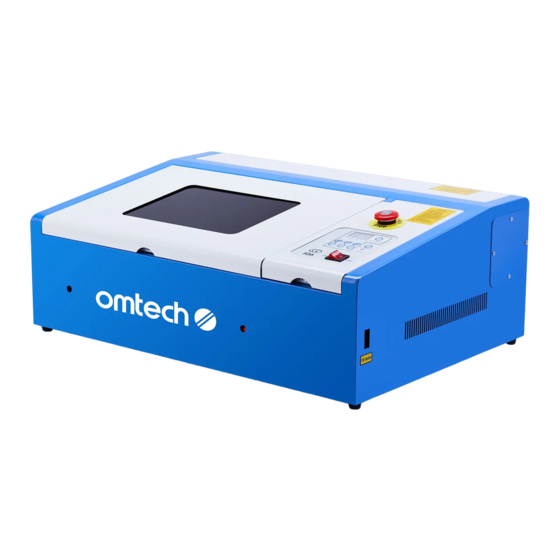
Chapter 1: Overview 1.1 Appearance (Varies slightly by model) From left to right, the front and top of the laser engraver includes the main bay and the control panel. (See 3.1 for details & variants). Fig. 1–1. Front & top sides (exterior). From left to right, the back of the laser engraver includes the connection port for the power cord, the terminal for the engraver’s electrical grounding (See 2.4), the exhaust fan (See 2.3), and the water tubes for the cooling system (See 2.2). - Page 7 Inside the main bay (Fig. 1–3), there is the optical path of the laser (Fig. 1–6). Fig. 1–3. Main bay (interior). The optical path consists of three reflective mirrors and one focus lens: The 1st mirror (1# in Fig. 1–4) is near the laser tube’s discharge outlet in the upper left corner of the machine.
-
Page 8: Accessories
Fig. 1–6. Optical path diagram. Your 3020 laser engraver works by emitting a powerful laser beam from its laser tube, reflecting that beam off of the three mirrors, focusing its power through the focus lens, and using this focused light to burn designs into materials. - Page 9 A collapsible exhaust pipe (Fig. 1–8) used to vent fumes produced by processed materials during the engrav- ing process. Fig. 1–8. Collapsible exhaust pipe. A bag containing various other accessories (Fig. 1 – 9), including: the engraver’s power cable, a USB 2.0 cable, and a CD-ROM with software, a software protection dongle, a roll of double-sided tape, a 0.28″...
-
Page 10: Chapter 2: Installation And Initial Adjustments
Chapter 2: Installation & Initial Adjustments A complete working system is composed of the laser engraving machine, its exhaust fan & pipe, its water pump & tank, and a USB cable. Users can configure the associated computers, printers, scanners and so on to suit their needs by themselves. 2.1. - Page 11 2.3. Install the exhaust pipe Install the exhaust pipe to the fan as shown in Fig. 2 – 2 below. The pipe can be expanded to a full length of about 1.5 metres (5 ft.). The other end of the pipe should be connected to a dedicated purifier or placed out a window.
-
Page 12: Chapter 3: Operation
Chapter 3: Operation Users are again advised to familiarize themselves thoroughly with the Safety instructions on pages 1 & 2, these operation guidelines, and the instructions marked “Attention” on the control panels. Operate the laser engraver only in accordance with all of these. 3.1 Control Panel The control panel is used to operate the machine. - Page 13 (3) 10, 1, 0.1 Buttons These buttons are used to adjust laser’s power in increments of 10%, 1%, and % respectively. As expected, + increases the power by the appropriate increment. – decreases the power by the appropriate increment. (4) Laser Power Display This displays the current power of the laser as a percent of its maximum intensity.
-
Page 14: Operation Procedure
(3) Test Switch When the on/off switch and the laser switch are both on, pressing the test switch button will fire the laser. This button will be used when adjusting laser power with the current regulation knob and when aligning the laser beam. (4) Current Knob This knob regulates the laser’s power, as shown in the current meter beside it. - Page 15 Fig. 3–2-1. Fig. 3–2-2. Fig. 3–2-3. Fig. 3–2-4. Step Three: Select the Placement of the Engraving Move the placement of the design in the software to move the laser head to the correct location. (1) Open LaserDRW.
- Page 16 (2) Select ENGRAVE in the ENGRAVE menu. (3) Select the appropriate FRAME for the image.
- Page 17 (4) Use REFER to select the proper alignment of your design with the selected position. (5) Drag the design to the correct location in the grid to position the laser head correctly over the materi- Step Four: Select a Power Setting On the machine, select the laser power you wish to use.
-
Page 18: Chapter 4: First Time User's Guide
Chapter 4: First Time User’s Guide The following is an extra guide on how to connect your machine to your PC and how to create and engrave a simple design using the copy of LaserDRW provided with your machine. For general information and installation instructions, see the separate engraver and software manuals. - Page 19 4) Once you have LaserDRW open, go to the top toolbar and click on “Engrave”, then “Device initialize.” This menu will open: Make sure that your Mainboard and Device ID match your machine. You can find your machine’s Mainboard and Device ID on its motherboard. To access the motherboard, first make sure you have the machine turned off and then unscrew the control lid.
- Page 20 Select your Model Number and type in your Device ID accordingly.
- Page 21 Press “Apply” and then “Ok”. You may be asked to restart the program. If so, close and reopen the program. Close and refasten the cover lid. 5) Turn on your machine. You will now be able to control the machine with your PC. 6) To test out connectivity, use the Square Tool to draw a small rectangle.
- Page 22 8) In the Engraving Manager screen that appears, you can adjust and control the positioning of the laser head and your image by clicking and dragging the origin (the center of the blue cross). 7) Press “Engrave” on the Menu and you will hear the machine reset to its origin.
- Page 23 9) Before engraving or cutting, you must make sure that the file you want to process is being sent to the machine and not to another location. Make sure you have this box unchecked. (Clicking it saves your file instead of engraving it.) 10) As you can see, the rectangle is placed below and to the right of the origin at the center of the blue cross.
- Page 24 11) Place your material on the bed and position the laser head accordingly. Once you are ready press the “Starting” option to begin. Make sure you have selected your desired wattage (power setting) using the control board on the machine.
- Page 25 12) Some models are equipped with a red laser guide that will mark the position of the laser head, initially located at the origin (the center of the blue cross you see on your computer screen). This example can still be followed through even if your model does not have the extra laser guide.
- Page 26 As you can see the laser now engraves your design in the upper right quadrant, up and to the right of the origin. Keep this feature in mind when you are setting up your material and jobs. Always keep the cover lid closed while processing jobs. 14) Refer to the software and engraver manuals for additional options.
-
Page 27: Chapter 5: Avoiding Problems
Chapter 5: Avoiding Problems Safe, stable use of your machine is inseparable from its proper operation and normal maintenance. If problems do arise, consult the troubleshooting guide at the end of this chapter. For if that does not resolve your issue, contact us or a specialized repair service. Do not open or attempt to repair this class 4 laser machine without training. -
Page 28: Optical Path Adjustment
5. Inspect the Alignment of the Engraver’s Optical Path Periodically Because the mirrors of your engraver’s optical path are fixed but the focus lens can acquire bias during operation, some optical path offset is possible. For best results, repeat the “Optical Path Alignment” (4.2) procedure before every project. - Page 29 (3) Test the alignment of the first and second mirrors when close Put the double-sided adhesive tape on second mirror (2#). Move the X-axis beam to Position A (Fig. 4 – 2) near the laser tube. Push the Test Switch button to activate the laser tube and produce a spot on the tape.
- Page 30 (4) Test the alignment of the first and second mirrors when distant When the first and second mirrors are well-aligned in Position A, slowly and gently move the X-axis beam to Position B (Figure 4 – 4) far away from the laser tube. Push the Test Switch button to activate the laser and produce a second spot on the tape on the second mirror.
- Page 31 If the laser spot is not in the center of the third mirror, you will need to adjust the angle of the second mirror using the knobs behind it (Fig. 4–6). These are similar to the knobs behind the first mirror described in Step 3 above and work identically. Figure 4–6.
- Page 32 Again, if the first and second spots on the tape are not identically placed, repeat the process of adjusting the second mirror’s knobs described in Step 5 above until the two spots overlap. (7) Test the alignment of the third mirror with the focus lens Put the double-sided adhesive tape on the hole at the top of the laser head beneath the third mirror.
-
Page 33: Troubleshooting
5.3 Troubleshooting Nothing happens when the engraver is turned on. Check the power cord and fuses. Nonstop laser. Check the electrical grounding wire and connections. Light comes on during operation. Check the water cooling system. If it is not operating smoothly, clean the water tank and pump and replace the distilled water. - Page 34 QR code to the right. Come join the OMTech community at our official laser group on Facebook or visit the company forums at omtechlaser.com! Check our YouTube channel for helpful hints and instructional videos.
- Page 35 F M M - 4 W 3 2 - U K Rev. 3 Dec. 2021...
Need help?
Do you have a question about the 3020 and is the answer not in the manual?
Questions and answers