Table of Contents
Advertisement
Quick Links
Advertisement
Table of Contents

Summary of Contents for HPS N Series
- Page 1 OWNERS MANUAL (Ref. N-line manual V3.06) N-LINE PANEL MOUNT, DESKTOP, REARMOUNT...
-
Page 2: Table Of Contents
N-LINE OWNERS MANUAL Contents Revision history ..................................4 About this manual ..................................4 Disclaimer ....................................4 Box contents and available options ............................5 Description ....................................7 Product identification................................. 7 Safety precautions..................................8 Installation....................................9 Mounting the monitor ............................... 9 8.1.1 Panel mount .................................. - Page 3 N-LINE OWNERS MANUAL 10.6 Model related specifications ............................29 10.7 Pin assignments ................................30 Pixel policy (ISO 13406-2 Scan Guidelines ) ..........................32 Sticking image ..................................33 P 3/33...
-
Page 4: Revision History
Further, We reserve the right to revise this publication and to make changes from time to time in the contents hereof without obligation of HPS Industrial B.V to notify any person of such revision or changes. -
Page 5: Box Contents And Available Options
N-LINE OWNERS MANUAL 4 Box contents and available options Please check the box contents right after receiving the equipment. The contents depend on the options ordered. Image Description Remark Monitor VGA cable (15p HD-Sub) DVI-D Cable HDMI Cable Optional 110/230VAC input: External power adapter N.a. - Page 6 N-LINE OWNERS MANUAL Otional Kiosk mounting: Mounting brackets with M5x50 screws Panel mount model only and M5 nuts Optional Rear mounting: Mounting brackets with M4 screw Rear mount model only External dimming/central dimming: External encoder or potentiometer with Can be mounted on a 1mm or 4mm LIN-Bus and LED-backlight frontplate.
-
Page 7: Description
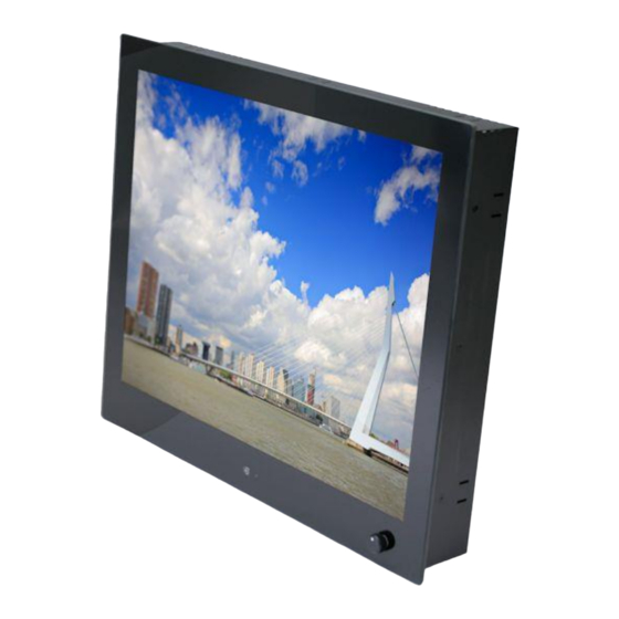
N-LINE OWNERS MANUAL 5 Description N-Line monitors are designed for industrial and marine environments. Special attention has been taken in account regarding robustness, easy installation and stylish appearance. This product is meant to be used indoor only, unless otherwise specified. With the right installation, proper operation and sufficient maintenance you will enjoy the monitor for years to come. -
Page 8: Safety Precautions
N-LINE OWNERS MANUAL 7 Safety precautions • Remove power if the monitor is not used for a longer period. This will also result in a longer lifetime of the backlight lamps. • The cover glass or touch sensor is made of regular (or hardened) glass. This can be scratched or even broken in pieces by hitting it •... -
Page 9: Installation
N-LINE OWNERS MANUAL 8 Installation The N-Line consists of 3 models: Panel mount, Vesa Mount and Rear Mount. The first part of this chapter describes the universal installation of all models. Please refer to the corresponding paragraphs below for more detailed mounting description per model. -
Page 10: Vesa Mount
N-LINE OWNERS MANUAL • Gently slide the monitor in the cutout. Do not mechanically force any part of the monitor during installation. • Install all mounting brackets at the back side using a 2,5mm hex key. To avoid damaging the housing, do not force the screws. -
Page 11: Connecting I/O
N-LINE OWNERS MANUAL 8.2 Connecting I/O Before connecting any I/O and power, make sure a correct GND connection has been made: Connect the unit to ground using the M4 screw in the I/O section marked with the grounding symbol: Make sure all connections are firmly fixed to the unit before powering up. For details regarding pin layouts, please refer to the chapter 10.7 Pin assignments. -
Page 12: Extended I/O, Ncom And (External) Dimming
N-LINE OWNERS MANUAL 8.2.2 Extended I/O, NCOM and (external) dimming Notes: 1- Only one power input can be selected when ordering the monitor. 12VDC is standard, 9~34VDC is optional. 2- The most right Power inputs 12VDC and 12VDC(F) are reserved power inputs. These are only available on special request 9~36VDC input –... -
Page 13: Front Controls
N-LINE OWNERS MANUAL 8.3 Front controls Depending on the model you have chosen, the following controls can be found at the front side of the unit: OSD MENU Description OSD MENU Description Dim knob Dimming knob 1. Potentiometer for backlight brightness: rotate CW to increase and CCW to decrease 2. -
Page 14: Setup For Operation (Osd-Menu)
N-LINE OWNERS MANUAL 8.4 Setup for Operation (OSD-menu) The OSD (On Screen Display) provides certain functions to have clear image and others. This monitor supports 5 buttons OSD Menu operation as a standard. The status-LED gives information about the signal status: Green OSD item Function Hotkey function... -
Page 15: Osd Status Led
N-LINE OWNERS MANUAL Power Save Adjust the Power Save time. (0 ~ 120Min) Zoom Mode Select the zoom mode. (Normal, OverScan, Zoom) Image Flip Image is reversed by vertical. (On, Off) Image Mirror Image is reversed by horizontal. (On, Off) Auto Source Detect the valid input source automatically. -
Page 16: Osd Menu "Picture
N-LINE OWNERS MANUAL 8.4.3 OSD menu “Picture” Symbol Main menu Sub Menu Signal source RGB (VGA)/DVI: Picture Mode Standard / Dynamic / User / Mild Contrast 0 ~ 100 Brightness 0 ~ 100 Colour 0 ~ 100 Sharpness 0 ~ 100 Colour Temp Color Mode: Warm / Medium / Cool / User... -
Page 17: Osd Menu "Function
N-LINE OWNERS MANUAL 8.4.4 OSD menu “Function” Symbol Main menu Sub Menu Power Save Off ~ 120 min.(off, 0.5, 1, 2, 5, 10, 30, 60, 120) Zoom Mode Normal / OverScan / Zoom (for CVBS & HDMI ) Aspect Auto / 16 : 9 / 4 : 3 / Fill Image Flip ON / OFF Image Mirror... -
Page 18: Osd Menu "Setup
N-LINE OWNERS MANUAL 8.4.5 OSD menu “Setup” Symbol Main menu Sub Menu Serial Port Baud Rate 1200 ~ 57600 Data 5bit ~ 8bit Parity None / Odd / Even Stop 1bit User Assign KeyPad > Backlight, Keypad < Volume, Contrast, Flip/Flop, Image Flip, Image Mirror,... -
Page 19: Engineering Osd With Dimming Encoder
N-LINE OWNERS MANUAL 8.5 Engineering OSD with dimming encoder N-Line monitors with option dimming are prepared for OSD-control by encoder-knob or 3-button dimming control. When using option potentiometer, only the power function is available. Please refere to the flow chart below for instructions: Symbol Encoder... -
Page 20: Touch Screen
N-LINE OWNERS MANUAL 8.6 Touch screen 8.6.1 Projected capacitive touch screen When using projected capacitive touch screen with USB connection you will NOT need to install any drivers. There is no further calibration needed, it is all factory set. The surface of the touch screen is pure glass. Scratches will not effect proper operation. The touch screen can be used with bare finger and even with thin gloves. -
Page 21: Trouble Shooting
N-LINE OWNERS MANUAL 9 Trouble shooting 9.1 Power Symptom Problem Action • • No status LED indication (with No power to the video Check proper pinning of power internal DC/DC converter) board connections • Check proper fitting of the wires in the screw connector •... -
Page 22: Dimming Control
N-LINE OWNERS MANUAL Symptom Problem Action • • • Black screen No power Check polarity of power wires • • No valid input Check input signal • • Monitor in Check color OSD led. Red:→ push standby/sleepmode dimming knob or standby button from •... -
Page 23: Specifications
N-LINE OWNERS MANUAL Symptom Problem Action • • • Resistive touch: • • • Touch not working. No drivers installed Install driver for RS232. For latest drivers visit www.eeti.com.tw/drivers.html • perform a 4-pointscalibration. Still not • • Bad cursor Poor calibration accurate: perform a 9- or 25-points •... -
Page 24: Applicable Graphic Mode
N-LINE OWNERS MANUAL 10.1.2 Applicable Graphic Mode The microprocessor measures the H-sync, V-sync and V-sync/H-sync polarity for RGB inputs, and uses this timing information to control all of the display operation to get the proper image on a screen. The monitor can detect all VESA standard and MAC Graphic modes shown on the table below and provide more clear and stable image on a screen. -
Page 25: Dimensions K, Ke, Kg And Kge Models
N-LINE OWNERS MANUAL 10.2 Dimensions K, KE, KG and KGE models Model (K, KG) (KE, KGE) (K, KE) (KG, KGE) (K, KG) (KE, KGE) N104 211.4 227.4 262.4 244.4 193.4 209.4 N106 195.6 288.2 270.2 177.6 N121 257.3 301.8 283.6 239.1 N121W 228.2... -
Page 26: Dimensions D And De Models
N-LINE OWNERS MANUAL 10.3 Dimensions D and DE models Model VESA (DE) (D, DE) (DG, DGE) 182.7 223.0 93.7 75x35 N104 207.7 242.4 86.2 N121 237.4 281.6 100.6 N150 285.1 343.1 122.3 N156 252.8 383.8 107.3 N170 322.0 376.9 140.9 N190 357.5 412.6... -
Page 27: Dimensions R Models
N-LINE OWNERS MANUAL 10.4 Dimensions R models Model N104 188.8 239.8 59.0 292.8 N106 265.6 59.0 318.6 N121 N121W N150 266.5 340.5 59.0 393.5 N154 243.0 366.0 59.0 419.0 N156 N170 302.9 374.3 59.0 427.3 N185 N190 336.6 410.0 59.0 463.0 N215 N230... -
Page 28: Electrical And Environmental
N-LINE OWNERS MANUAL 10.5 Electrical and environmental In this manual all basic specifications are summarized. If you need more detailed info please contact us. Item Item Unit Power DC Input 12VDC -plug 11.2 12.7 Ext. DC Power (*1 36.0 Desktop PSU 12VDC AC Input 100-240V ~ 1,8A, 50-60Hz DC Output... -
Page 29: Model Related Specifications
N-LINE OWNERS MANUAL 10.6 Model related specifications Parameter N104 N106 N121 N121W N150 N154 N156 N170 N185 N190 N215 N230 N240 N241 N270 N320 N420 Active area (mm) 170x128 211x158 231x138 246x148 261x163 304x228 331x207 344.2x193.5 337.9x270.3 409.8x230.4 376.3x301.1 477x268 509.2x286.4 531.4x298.9 518.4x324.0... -
Page 30: Pin Assignments
N-LINE OWNERS MANUAL 10.7 Pin assignments DVI Input (DVI D-Type) (L-R row-wise) Function Function Function Function Function TX2- DDC CLK TX 1/3 Shield H/P Detect TX2+ DDC data TX0 - TXClk Shield Data2/4 shield TX0 + TXCLK+ TX1- DC +5V TX0/5 Shield TXCLK- TX1+... - Page 31 N-LINE OWNERS MANUAL NCOM IN (RJ45) Function Function Function Function Function 12V (LIN power) LIN-bus RS485 D+ RS485 D- NCOM OUT (RJ45) Function Function Function Function Function RS485 D+ RS485 D- This option is not part of certification RS232 touch (DB9-female) (R-L row-wise) Function Function...
-
Page 32: Pixel Policy (Iso 13406-2 Scan Guidelines )
N-LINE OWNERS MANUAL 11 Pixel policy (ISO 13406-2 Scan Guidelines ) TFT monitors are precise units made up of a set number of pixels. Unfortunately this can be seen as a weakness. Pixels are made up the three sub-pixels being red, green and blue each consisting of their own transistors that controls whether or not it lights up. -
Page 33: Sticking Image
N-LINE OWNERS MANUAL Type 4) fault cluster, the number of defective pixels in a 5 x 5 pixel square. Class I monitors are guaranteed products which do not have any defects at all . Class II specification consists of the following faults permissible: 2 x Type 1, 2 x Type 2, 5 x Type 3 and 2 x Type 4. We deliver TFT Monitors in accordance to ISO 13406-2 Class II.
Need help?
Do you have a question about the N Series and is the answer not in the manual?
Questions and answers