Table of Contents
Advertisement
Quick Links
Advertisement
Table of Contents

Related Manuals for TBB power ES100

Summary of Contents for TBB power ES100
- Page 2 ES100 ESS Unit User Manual...
- Page 3 ES100 ESS Unit User Manual WARNING:HIGH VOLTAGE IN SIDE CAUTION:THE DC FUSE MUST HAVE BEENTURNED OFF BEFORE SERVICING MADE IN CHINA...
- Page 4 ES100 ESS Unit user manual Statement of Law Copyright of this document belongs to TBB Power Co., Ltd. No part of this documentation maybe excerpted, reproduced, translated, annotated or duplicated in any form or by any means without the prior written permission of TBB Power Co., Ltd. All Rights Reserved.
- Page 5 Preface Manual declaration The ES100 lithium iron phosphate battery can be widely applied to energy storage systems including backup power, solar off grid, solar energy storage, solar hybrid, PV power generation, etc. This user manual details its basic structure, parameters, basic procedures and ways of installation...
-
Page 6: Table Of Contents
ES100 ESS Unit user manual Contents B4850 ESS Unit User Manual 1. Introduction ..........................1 1.1 Brief Introduction ........................ 1 1.2 Product Properties ......................1 1.3 Product identity definition ....................2 2. Product Specification ........................3 2.1 Size and Weight ......................... 3 2.2 Performance Parameter ..................... -
Page 7: Introduction
ES100 lithium iron phosphate battery system is a standard battery system unit. Customers can choose a certain number of ES100 according to their needs, to form a larger capacity battery storage through parallel connection, to meet the user's long-term power supply needs. The product is especially suitable for applications with high operating temperatures and limited installation space, requiring long power backup time and long service life. -
Page 8: Product Identity Definition
ES100 ESS Unit user manual 1.3 Product identity definition B4850 ESS Unit User Manual Figure 1-1 Battery Energy Storage System nameplate Battery voltage is higher than safe voltage, direct contact with electric shock hazard. Be careful with your actions and be aware of the dangers. -
Page 9: Product Specification
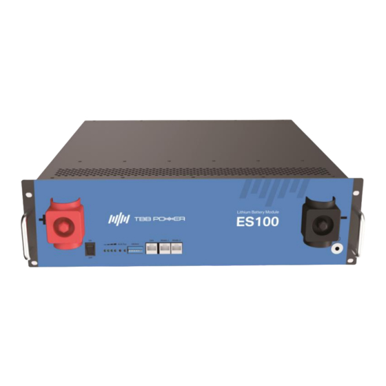
ES100 ESS Unit user manual 2. Product Specification 2.1 Size and Weight Table 2-1 ES100 Device size Nominal Nominal Product Dimension Weight Voltage Capacity ES100 DC48V 105Ah 482.6×450×133.4mm 40kg... -
Page 10: Performance Parameter
Maximum discharge current (A) Final discharge voltage(V) Cycle Life 90%DOD,6000 cycles life Charging temperature range 0℃~+55℃ Discharging temperature range -20℃~+55℃ -20℃~+45℃ 1month Storage temperature 0℃~+35℃ 3months 2.2.1 Front Panel Interface Definition 3 4 5 6 Figure 2-2 The interface of ES100... -
Page 11: Address
ES100 ESS Unit user manual Table 2-3 Interface Definition Item Name Definition Connect to battery positive output cable or Positive socket positive parallel cable OFF/ON button, must be on the "ON" state Power switch when in use The number of green lights on shows the remaining battery power. - Page 12 ES100 ESS Unit user manual Table 2-4 Slave setting DIP switch Address Description Address 1 Address 2 Address 3 Address 4 Address 5 Address 6 Address 7 Address 8 Address 28 Address 29 Address 30 Address 31 Table 2-5 Master setting...
-
Page 13: Communication Port Definition
ES100 ESS Unit user manual 2.2.3 Communication Port Definition The product provides three RJ45 connectors respectively for one CAN port and two RS485 communication ports. All pins of the two connectors RS485-1 and RS485-2, are connected in parallel, so their interface definitions are completely the same. -
Page 14: Battery Management System (Bms)
ES100 ESS Unit user manual 2.3 Battery Management System (BMS) 2.3.1 Voltage Protection Low Voltage Protection during Discharging Process: When the voltage of a battery cell or the total voltage is lower than the protection value, the battery will start over-discharging protection during the discharging process and the battery ALM indicator will be always on. -
Page 15: Installation And Configuration
ES100 ESS Unit user manual 3. Installation and Configuration 3.1 Ready for installation Safety Requirement This system can only be installed by personnel who have been trained on the power supply system and have sufficient knowledge of the power system. -
Page 16: Tools And Data
ES100 ESS Unit user manual 3.1.2 Tools and data Hardware tool Tools and meters that may be used are shown in table 3-1. Table 3-1 Tool instrument Name Screwdriver (word, cross) AVO meter Wrench Clamp meter Inclined pliers Insulating tape... -
Page 17: Unpacking Inspection
ES100 ESS Unit user manual 3.1.4 Unpacking inspection When the equipment arrives at the installation site, loading and unloading should be carried out according to the rules and regulations, to prevent it from being exposed to sun and rain. -
Page 18: Engineering Coordination
ES100 ESS Unit user manual 3.1.5 Engineering coordination Attention should be paid to the following items before construction: Power cable specification. The power cable specification shall meet the requirements of maximum discharge current for each product. Mounting space and bearing capacity. -
Page 19: Installation Preparation
ES100 ESS Unit user manual 3.2.1 Installation preparation 1. Prepare equipment and tools for installation. 2. Check the battery and confirm that the ON/OFF switch is in the "OFF" state to ensure no live operation. 3.2.2 Mechanical installation Installation method 1: With Cabinet installation 1. - Page 20 ES100 ESS Unit user manual 2. Complete insert the battery into the bracket as figure3-5, pay attention to pushing the battery to the buckle position. Figure 3-5 3. Place another bracket in the rear of the battery and push it to the buckle position.
-
Page 21: Electrical Installation
ES100 ESS Unit user manual 3.2.3 Electrical installation Before connecting the power cables, use multi-meter to measure cable continuity, short circuit, confirm the anode and cathode, and accurately mark the cable labels. Measuring methods: Cable availability: select the buzzer and use the probe to measure the ends of the same color cable. -
Page 22: Use, Maintenance And Troubleshooting
ES100 ESS Unit user manual 4. Use, maintenance and troubleshooting 4.1 Battery system usage and operation instructions After completing the electrical connection, please follow these steps to start the battery system. 1. Refer to 2.3.2 for the definition of the DIP switch and prepare for the DIP before turning on the system, and then turn the switch ON/OFF to ON. -
Page 23: Alarm Description And Handling
ES100 ESS Unit user manual 4.2 Alarm description and handling When the protection action or fault occurs to the system, the alarm signal will be shown through the working status indicator on the front panel of the battery. The network management can query the specific alarm categories. - Page 24 ES100 ESS Unit user manual...
Need help?
Do you have a question about the ES100 and is the answer not in the manual?
Questions and answers