
Summary of Contents for MKSEMI MK8000 EVB
- Page 1 MK8000 EVB Quick Start Guide Mauna Kea Semiconductor Confidential October 14, 2022 1 of 23...
- Page 2 MK8000 EVB Quick Start Guide Customer Support Document Revision History Revision Date Description Author V0.1 2022-02-14 Initial version Z. Xing Mauna Kea Semiconductor Confidential Rev 0.3 October 14, 2022 2 of 23...
-
Page 3: Table Of Contents
MK8000 EVB Quick Start Guide Table of Contents Overview ..............................6 What’s in the box ............................. 6 MKSemi EVB Hardware Setup ......................6 Power supply connection ........................... 6 Power supply configuration ........................6 Function Description of Jumper Pins ..................... 7 3.4.1... - Page 4 MK8000 EVB Quick Start Guide Table of Figures Figure 1 MK8000 evaluation kit ....................................6 Figure 2 Front and back side of MK8000 EVB ..............................7 Figure 3 Anchor connection ....................................... 9 Figure 4 Tag connection ......................................10 Figure 5 Installation of device description file for IAR System ......................... 12 Figure 6 MK8000 SDK package .....................................
- Page 5 MK8000 EVB Quick Start Guide List of Tables Table 1 Jumper configuration for different supply voltage ........................... 7 Table 2 Jumper Pin Description ....................................7 Table 3 Anchor side hardware connection in standalone mode ......................... 8 Table 4 Tag side hardware connection in standalone mode ........................9 Table 5 hardware settings for MKTool mode ..............................
-
Page 6: Overview
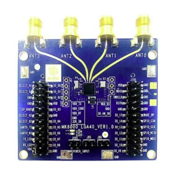
This chapter provides step-by-step instructions for setting up the evaluation kit. Power supply connection Figure 2 shows the front and back sides of the MK8000 EVB. J105 is the jumper for power supply. J105(+) connects to VCC and J105(-) connects to GND. -
Page 7: Function Description Of Jumper Pins
Function Description of Jumper Pins The MK8000 EVB has two rows of jumpers that are connected to the I/Os of the chip to offer the flexibility of configuration and programming. Table 2 describes the functionality of the jumper pins on the MK8000 EVB. -
Page 8: Anchor Hardware Setup In Standalone Mode
UART0 RXD Standalone mode hardware setup The MK8000 EVB standalone mode needs two MK8000 EVBs to perform the evaluation. One EVB is configured as an Anchor Role and connected to a 4-element linear array antenna, the other EVB is configured as a Tag role and connected to a single element antenna. -
Page 9: Tag Hardware Setup In Standalone Mode
MK8000 EVB Quick Start Guide Figure 3 Anchor connection 3.4.2 Tag hardware setup in standalone mode Table 4 shows the detail of the Tag hardware connection in standalone mode and Figure 4 shows the tag after connection. In standalone mode, the USB adapter at the tag side is used for power supply only. -
Page 10: Mktool Mode Hardware Setup
Figure 4 Tag connection MKTool mode hardware setup The MK8000 EVB MKTool mode needs two MK8000 EVBs and Windows laptops with MKTool software installed. MKTool is a Windows application program developed by MKSEMI and used to configure the chip and the EVB, perform and control the MK8000 chipset evaluation. It has a GUI interface for configuration and results display. -
Page 11: Isp Mode Hardware Setup
Based on either section 3.4 or 3.5, use flat ribbon wires to connect IO_03 to GND and ensure that the IO_03 is low when the MK8000 EVB is powered on, the EVB enters ISP mode and the firmware can be updated through UART0. -
Page 12: Software Setup
This chapter provides an overview of software setup of MK8000 EVB. Software setup is needed when MKTool mode is used in the testing and evaluation. There is no need to program the MK8000 EVB if Standalone mode is used in the test and evaluation. -
Page 13: Firmware Download
Before testing and evaluation, user needs to download the proper firmware into the MK8000 chipset. MKSEMI provides an application software, the ISPTool, to download the firmware. To download the firmware, user needs to connect the EVB to the laptop and get a proper COM port number in Windows Device Manager for this device and launch the ISPTool application. -
Page 14: Figure 7 Isptool Update Firmware - 0
MK8000 EVB Quick Start Guide Figure 7 ISPTOOL update firmware - 0 Figure 8 ISPTOOL update firmware – 1 Mauna Kea Semiconductor Confidential Rev 0.3 October 14, 2022 14 of 23... -
Page 15: Application Examples
MK8000 EVB Quick Start Guide 5. Application examples This chapter provides an introduction of procedures for two basic tests: Ranging and AoA Power consumption Ranging and AoA test At the beginning of test, the proper bin file should be downloaded to MK8000 EVBs. Get example project from the following locations then make the bin file or get bin file directly. -
Page 16: Mktool Mode
5.1.2.1 Tag configuration The tag is an MK8000 EVB which connects to single element antenna. To configure the tag, user needs to connect the EVB to the laptop and get a proper COM port number in Windows Device Manager for this device and launch the MKTool application. In MKTool, do the following steps: Mauna Kea Semiconductor Confidential Rev 0.3... -
Page 17: Figure 11 Mktool Mode Tag Side Configuration
5.1.2.2 Anchor configuration The Anchor is an MK8000 EVB which connects to 4-element linear array antenna. To configure the anchor, user needs to connect the EVB to the laptop and get a proper COM port number in Windows Device Manager for this device and launch the MKTool application. In MKTool, do the following steps: 1. -
Page 18: Figure 12 Mktool Mode Anchor Side Configuration
MK8000 EVB Quick Start Guide Figure 12 MKTool Mode Anchor side configuration Mauna Kea Semiconductor Confidential Rev 0.3 October 14, 2022 18 of 23... -
Page 19: Figure 13 Example Of Setup Of Ranging And Aoa Test In Mktool Mode
MK8000 EVB Quick Start Guide 5.1.2.3 Measurement setup and examples Figure 13 shows the typical measurement setup of using MKTool mode. Both the Anchor and the tag are set on plastic stands vertically and connected to laptop PCs. Figure 14 shows typical measurement results. -
Page 20: Coarse Measurement Of Current Consumption
5.2.1 Coarse measurement of current consumption This test uses the following the steps with a multimeter to measure the current of MK8000 EVB. 1. Power off the MK8000 EVB 2. Leave the J96 at the disconnect state and short the J95 3. -
Page 21: Fine Measurement Of Current Consumption
Fine measurement of current consumption This test uses the following steps with an oscilloscope to measure the fine current consumption of MK8000 EVB. The current consumption is equal to the voltage measured by the scope / the resistance of R145 (default value 1Ohm) 1. -
Page 22: Reference
MK8000 EVB Quick Start Guide 7. Reference [1] MK8000 Datasheet v0.82 [2] MKTool User Manual v0.5 [3] ISP user manual v0.5 8. FCC regulatory compliance statement §15.19 Statement This device complies with Part 15 of the FCC Rules. Operation is subject to the following two conditions: (1) this device may not cause harmful interference, and (2) this device must accept any interference received, including interference that may cause undesired operation. - Page 23 MK8000 EVB Quick Start Guide configurations, including portable configurations with respect to §2.1093 and difference antenna configurations. Antenna Change Notice to Host manufacturer If you desire to increase antenna gain and either change antenna type or use same antenna type certified, a...
Need help?
Do you have a question about the MK8000 EVB and is the answer not in the manual?
Questions and answers