Table of Contents
Advertisement
Quick Links
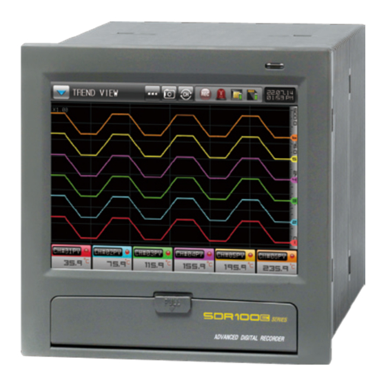
Instruction manual (Digital recorder)
It is a digital recorder without paper. It supports the high screen quality TFT_LCD touch screen and
SD card. It is a product with rapid graph searching function.
Being the controller market leader in the 21st century with the best technology
http://www.samwontech.com
Advertisement
Table of Contents

Summary of Contents for Samwon Tech SDR100E Series
- Page 1 Instruction manual (Digital recorder) It is a digital recorder without paper. It supports the high screen quality TFT_LCD touch screen and SD card. It is a product with rapid graph searching function. http://www.samwontech.com Being the controller market leader in the 21st century with the best technology...
- Page 2 Copyright Copyright© 2022 SAMWONTECHNOLOGY CO.,LTD. This instruction manual is a work protected by the copyright law. A part or entire of this manual shall not be copied, air sent, distributed, translated or changed into the form to be read by electronic media or machine without prior written consent of SAMWONTECHNOLOGY CO.,LTD.
-
Page 3: Table Of Contents
This manual is commonly used for SDR102E, SDR104E, SDR106E and SDR112E and SDR100E is written inside. Contents 10. Setting screen display‥ ‥‥‥‥‥‥‥‥‥‥‥‥‥‥‥‥‥‥56 01. Cautions (Instructions) for safety‥ ‥‥‥‥‥‥‥‥‥‥‥‥‥ 4 10-1. Setting screen display ‥‥‥‥‥‥‥‥‥‥‥‥‥‥‥‥‥‥‥‥‥ 56 1-1. Checking the product ‥‥‥‥‥‥‥‥‥‥‥‥‥‥‥‥‥‥‥‥‥‥‥4 10-2. -
Page 4: Cautions (Instructions) For Safety
Cautions (Instructions) for safety Thank you for your choice of out digital recorder (SDR100E). This manual describes the method of installation and use of the product. Cautions in this instruction manual Symbol marks for safety ■ Please deliver for the end user to possess always and keep it in the place accessible at any time. ■... -
Page 5: Checking The Product
Part Cautions (Instructions) for safety 1-1. Checking the product ‥‥‥‥‥‥‥‥‥‥‥‥‥ 4 1-2. Exterior and how to install ‥‥‥‥‥‥‥‥‥‥‥ 6 1-3. Wiring ‥‥‥‥‥‥‥‥‥‥‥‥‥‥‥‥‥‥‥‥ 9... - Page 6 01. Cautions (Instructions) for safety 1-1. Checking the product ● When the product is purchased, please check the damaged on the product by checking the exterior of the product. (1) Checking the specification of the ordered product ● Check whether the purchased product is identical with the ordered specification. ●...
- Page 7 (2) Check the parts inside the package ● Please check whether the following parts are included. SDR100E Series main body SD card Mount for fixing (Left : 2, Right : 2) Instruction manual (3) How to treat the damaged parts ●...
-
Page 8: Exterior And How To Install
1-2. Exterior and how to install (1) Installation location and environment Cautions for the installation location and environment Installation Precautions This product is an industrial product. Don’t put the device or the wiring which cause the noise near to this ●... - Page 9 (2) External dimension (Unit:mm) 2 ~ 7 (Panel thickness) (3) Panel cutting dimension (Unit:mm) 180(Minimum)
- Page 10 Fixing mount right (4) How to attach on the panel mount Fixing mount left *How to install the product Fixing mount right References Direction Fixing mount left ▶ Cut the panel to be installed. Refer to the of insertion [1-2(3) Panel cutting dimension] ▶...
-
Page 11: Wiring
1-3. Wiring Cautions ● Make the wiring after checking whether the wiring cable is applied for current with tester by switching off the main electric power in every supplied instrument. ● Never contact to the terminal because of the risk of electric shock during application of the current (Electric power on). ●... - Page 12 (2) Terminal layout Remote (DI/Option) Channel input (Channel 7~12) Electric power Relay output (Option) Switch Channel input (Channel 1~6) Ethernet RS485/232C...
- Page 13 (3) Electric power circuit ● Use the cable with equivalent or above the vinyl insulated cable (KSC3340) or electric cable for electric power circuit. ● Make the circuit for ground with the electric cable over 2mm and above the third class ground (Unver100Ω of ground resistance) ●...
-
Page 14: Operation And Setting
Part Operation and setting 2-1. Function and name of the display ‥‥‥‥‥‥‥13 2-2. Menu flow chart ‥‥‥‥‥‥‥‥‥‥‥‥‥‥‥‥14 2-3. Basic operation flow chart ‥‥‥‥‥‥‥‥‥‥‥16 2-4. Setting button operation ‥‥‥‥‥‥‥‥‥‥‥‥18 2-5. Warning message display ‥‥‥‥‥‥‥‥‥‥‥19 2-6. Parameter setting method ‥‥‥‥‥‥‥‥‥‥‥20... -
Page 15: Function And Name Of The Display
02. Operation and setting 2-1. Function and name of the display ● This product is a digital recorder designed in dialogue type touch screen for easy use. Cover (There are electric power switch, SD card insertion part, ① Mini USB when the cover is opened.) ②... -
Page 16: Menu Flow Chart
2-2. Menu flow chart Electric power ON Initial screen 1. Trend screen 2. Bar graph 3. Digital screen 4. Message input 5. (Graph record) Save Operation screen Graph recording 6. Internal memory, SD card, alarm status display 7. Search bar button 8. Capture button 9. - Page 17 1. Sensor type 2. Unit of display 3. Tag name 4. Dot position System setup Setting the sensor input 5. Sensor range 6. PV when S.OPN 7. Measurement method 1. Alarm Operation 2. 4 for each channel Alarm signal ● Type : PV upper limit, PV lower limit, within PV range, Out of PV range, Over PV ascending change ratio, under PV descending change ratio, within the deviation between channels, out of the deviation error between channels, sensor circuit short ●...
-
Page 18: Basic Operation Flow Chart
2-3. Basic operation flow chart The logo displaying screen and the initial screen are displayed sequentially when the electric power is switched ON after installation of the product and ԙ it converts to the graph recording screen automatically. It takes about 20 seconds in screen loading ԙ... - Page 19 Password input screen Screen without DI option Screen with DI option...
-
Page 20: Setting Button Operation
2-4. Setting button operation [Table 2-1] Button type Button operation It is used for inputting the general numbers and name. It is used for selection for one out of many types. It is used for selection for one out of more than 2 parameter setting. (ON / OFF state) It is used for selection of Y/N for the corresponding parameter. -
Page 21: Warning Message Display
2-5. Warning message display [Table 2-2] Display type Description Action In case of no insertion of SD card or error No insertion of SD card SD card checking No insertion of SD card creation In case of shortage of SD card saving Shortage of SD card capacity SD card deletion Shortage of SD card capacity... -
Page 22: Parameter Setting Method
2-6. Parameter setting method ● When is selected in basic setting button in the above [Table 2-1], the input key of the setting value is shown as followings and the data can be input. ● When the data out of the setting range is input, error message (“LIMIT ERROR”) is shown on the input data display window with the error sound (“Beep”) ▲... -
Page 23: Main Screen
Part Main screen... - Page 24 03. Main screen [Fig. 3-1] Main screen No. Main menu Description Move to the Start/Stop for graph saving screen ① GRAPH RECORD Move to the data (Graph) searching screen stored ② GRAPH SERACH in the internal memory/SD card ③ Move to the function and operation setting screen FUNCTION SET Move to the graph display option ④...
- Page 25 Part Graph recording setting 4-1. Graph recording screen ‥‥‥‥‥‥‥‥‥‥‥‥24...
-
Page 26: Graph Recording
04. Graph recording 4-1. Graph recording screen (1) Graph recording screen ● When the “Graph Record” is selected from [Fig. 3-1 Main screen], Symbol Description it is converted to “Graph recording screen.” The currently saving graph is searched as [Fig 4-13] ●... - Page 27 [Fig. 4-2] Screen in case of non saving the graph [Fig. 4-3] Screen in case of saving the graph (White screen) (Display of sub menu bar) Symbol Description Convert to [Fig. 3-1 Main screen ] Convert to [Fig. 4-2 Screen in case of non saving the graph] Convert to [Fig.
- Page 28 [Fig. 4-5] Digital graph screen [Fig. 4-7] The screen selected with in message input [Fig. 4-6] The message input screen [Fig. 4-8] The screen selected with in message input...
- Page 29 [Fig. 4-9] PV graph saving screen [Fig. 4-11] The screen for setting the file name in graph saving Reference ▶ The file name in saving the PV graph use maximum 8 character combination. ▶ The file name is not set separately in case of PV graph saving. In case of using the input name as it is, the figures at the suffix are set as current time.
- Page 30 (2) Graph recording saving screen ● The screen for saving the graph record is composed of 3 screens. ● Each channel is displayed with unique color. ● The name of each channel can be set. [Fig. 4-12] Operation screen in case of saving graph (Vertical) The current PV is displayed on the scale bar.
- Page 31 Reference ▶ The back ground color is changeable into black or white ▶ The direction of the graph is changeable into vertical or horizontal ▶ The message can be input. ▶ The storage period can be changed ▶ The measured data for the corresponding channel is displayed in alarming and the warning lamp is operated [Fig 4-13] Operation screen for PV graph (Horizontal) storing...
- Page 32 (3) Graph navigation screen ● If the button is selected, the graph currently being saved is stopped and [Fig. 4-13]. ● Select the button to switch to the currently saved graph screen. [Fig. 4-13] Current saved graph navigation screen ① Create navigation lines and navigation button bars Blue navigation line on the graph Displays the measurement value for each channel with the current...
- Page 33 [Fig. 4-14] Section view button screen [Fig. 4-15] All view button screen View section References ▶ : View all button / : View section button ▶ When this button is pressed, it switches to button It switches from [Fig. 4-14] Section view button screen to [Fig.
- Page 34 Reference ▶ : Note mode button / : Button in running note mode ▶ Note mode does not work when in full view ▶ When you want to delete a created note, you can delete it by discontinuing note mode and then executing note mode again ▶...
- Page 35 Note mode (Write note) Note mode (Delete note) ① ( Button) ⇨ ② (Choose color) ⇨ ③ Write (Note) ① ( Button) ⇨ ② ( Button) delete ● ● When not in a note mode after writing a note (View section) When not in a note mode after writing a note (View all) It displays note created when viewing section on trend screen It displays note created in full view on trend screen...
-
Page 36: Graph Searching
Part Graph searching 5-1. Graph view ‥‥‥‥‥‥‥‥‥‥‥‥‥‥‥‥‥‥35 5-2. Data searching ‥‥‥‥‥‥‥‥‥‥‥‥‥‥‥‥36... - Page 37 05. Graph searching 5-1. Graph view ● When the “Graph search” is selected from the [Fig.3-1 Main screen], it converted to ‘Graph searching screen.” ● It is a screen to search the file stored in the internal memory and SD card. ●...
-
Page 38: Data Searching
5-2. Data searching Press the button to display the files stored in the internal ① memory. Internal memory / SD card file selection ② : Internal memory ● : SD card ● Used to open the selected PV file. ③ Select the desired file and press the button to open it. -
Page 39: Function Setting
Part Function setting... - Page 40 Function setting Flow chart flow chart [Fig. 6-1] Function setting screen #1 [Fig. 6-2] Function setting screen #2 Part 06...
- Page 41 06. Function setting ● When “Function set” is selected from [fig. 3-1 Main screen], it is converted to “Function setting screen.” ● It is the screen for setting the additional function of the product. [Refer 1] [Fig. 6-1] Function setting screen #1 [Fig.
- Page 42 Instruction Description RECORDING CYCLE Setting the saving period TIME Saving period adopted to the INTERVAL RECORD MEDIA Setting the place to save the recorded graph Saving into the internal memory Saving into the SD card BOTH Saving into the internal memory and SD card simultaneously POWER STOP MODE Setting the recovery operation in case of blackout STOP...
- Page 43 Reference ▶ The graph is not saved when the SD card is not inserted after setting the saving media with SD card or both of them. ▶ The graph is not saved when the memory on the SD card is full. ▶...
- Page 44 [Fig. 6-5] PV display type screen (Tag) [Fig. 6-7] Screen for setting the main button restriction Reference ▶ [Fig. 6-7] is the screen for setting the main button restriction ▶ The password setting keypad is displayed when the main button is pressed in recording screen ▶...
- Page 45 Parameter Setting range Unit Initial value RECORDING CYCLE 0.5 sec, 1 sec, 2 sec, 5 sec, 10 sec, 20 sec, 30 sec, 1 min 1 sec RECORD MEDIA MEM, SD, BOTH POWER STOP MODE STOP, HOT STOP RESTRICT OF MAIN UNUSE, USE UNUSE BASIC SCREEN...
-
Page 46: Graph Option
Part Graph option 7-1. Graph display option (Graph recording screen)‥ ‥‥‥‥‥‥‥‥‥‥ 46 7-2. Graph display option (Graph searching screen)‥‥‥‥‥‥‥‥‥‥‥ 47... - Page 47 Graph option flow chart Flow chart [Fig. 7-1] Graph display option (Graph recording screen) [Fig. 7-2] Graph display option (Graph searching screen) Part 07...
-
Page 48: Graph Display Option (Graph Recording Screen)
07. Graph option 7-1. Graph display option (Graph recording screen) ● When “Graph option” is selected from [Fig. 3-1 Main screen], Instruction Description it is converted to “Graph display option screen.” TREND DIRETION Setting of the direction of graph recording screen ●... -
Page 49: Graph Display Option (Graph Searching Screen)
7-2. Graph display option (Graph searching screen) ● It is the screen for setting the parameter adopted for the graph recording screen. Instruction Description Setting of the direction of graph searching screen TREND DIRETION Y-AXIS The direction of the graph searching screen is displayed vertically. X-AXIS The direction of the graph searching screen is displayed horizontally. - Page 50 Graph recording screen basic line Graph searching screen basic line [Fig. 7-3] Screen for setting the reference line in graph [Fig. 7-4] Screen for setting the reference line in graph recording screen searching screen Parameter Setting range Unit Initial value TREND DIRECTION Y-AXIS, X-AXIS Y-AXIS...
-
Page 51: Setting Canned Message
Part Setting canned message... - Page 52 08. Setting canned message ● When “Canned message” is selected from [Fig. 3-1 Main screen], it is converted to “Setting canned message.” Instruction Description Setting the frequently used message in message input CANNED MESSAGE in recording screen Parameter Setting range Unit Initial value Graph display message 1...
-
Page 53: Setting Reserve Operation
Part Setting reserve operation... - Page 54 Flow chart for setting Flow chart reserve operation [Fig. 9-1] Screen for current time setting [Fig. 9-2] Screen for reserve time setting Part 09...
- Page 55 09. Setting reserve operation ● When “Reserve set operation” is selected from [Fig. 3-1 Main screen], it is converted to “Screen for setting current time, reserve storing time.” ● The current time, reserve operation time (Start/End) can be set. ● The reserve time is not changed during reserve and reserve operation. ●...
- Page 56 Parameter Setting range Unit Initial value CURRENT TIME(YEAR) 2000~2099 CURRENT TIME(MONTH) 1~12 CURRENT TIME(DATE) 1~31 CURRENT TIME(AM/PM) AM/PM CURRENT TIME(HOUR) 1~12 CURRENT TIME(MIN) 0~59 2011 RESERVE START TIME(YEAR) 2000~2099 RESERVE START TIME(MONTH) 1~12 RESERVE START TIME(DATE) 1~31 RESERVE START TIME(AM/PM) AM/PM RESERVE START TIME(HOUR) 1~12...
-
Page 57: Setting Screen Display
Part Setting screen display 10-1. Setting screen display ‥‥‥‥‥‥‥‥‥‥‥‥56 10-2. Touch screen calibration Seting ‥‥‥‥‥‥‥‥59 10-3. Internal memory management ‥‥‥‥‥‥‥‥‥61... - Page 58 10. Setting screen display 10-1. Setting screen display ● When “Screen Display set” is selected from [Fig. 3-1 Main screen], it is converted to “Screen display setting.” ● It is a screen to set the screen brightness and electricity saving time. Instruction Description Setting the Y/N for using buzzer sound...
- Page 59 [Fig. 10-2] Display of all digital graphs [Fig. 10-3] Display of digital graph group (Channel 1~6) [Fig. 10-3] Display of all digital groups (Channel 7~12)
- Page 60 [Fig. 10-4] Graph automatic conversion screen (Channel 1~6) [Fig. 10-5] Graph automatic conversion screen (Channel 7~12) Reference ▶ It is operated when there is no key action for a certain period of time (1 min) in recording screen. ▶ It is not operated when the automatic conversion is “0” in recording screen. ▶...
-
Page 61: Touch Screen Calibration Seting
10-2. Touch screen calibration Seting Press the red dot at the left / right upper, left / right bottom and center of the touch screen calibration screen, you can calibrate the touch screen. ԙ [Fig. 10-7] Touch screen calibration #2 [Fig. - Page 62 [Fig. 10-8] Touch screen calibration #3 [Fig. 10-9] Touch screen calibration #5 [Fig. 10-10] Touch screen calibration #4 [Fig. 10-11] Touch screen calibration #6...
-
Page 63: Internal Memory Management
10-3. Internal memory management ① PV graph folder list ② PV graph file list ③ Display of internal system memory capacity Copy the PV graph file selected from the file list to the SD card If there is no SD card option or while saving the PV graph on the ●... -
Page 64: Error History Display
Part Error history display... - Page 65 Flow chart for Error Flow chart history display [Fig. 11-1] 저장형식 화면 [Fig. 11-2] Screen for error history [Fig. 11-3] Screen for event history Part 11...
- Page 66 11. Error history display ● When “History display” is selected from [Fig. 3-1 Main screen], it is converted to “Screen for history display setting.” ● It is a screen for displaying the error, alarm and event history. ● It saves 100 errors, alarm and event history and the occurred history later are saved after deletion of the first saved history. [Fig.
- Page 67 [Fig. 11-2] Screen for event history Message contents Screen display Lettering color In power ON (Hot) POWER ON(HOT) White In record ON RECORD ON White In record OFF RECORD OFF White In record ON (Appointment) RECORD ON(RESERVE) White In record OFF (Appointment) RECORD OFF(RESERVE) White In record ON (Remote D11)
-
Page 68: Setting System Parameter
Part Setting system parameter... - Page 69 12. Setting system parameter ● Refer to [Fig. 3-1 Main Screen] for process of entering into the system parameter setting screen. ● Refer to [Fig. 2-3 Basic operation flow chart] system setting screen depending on DI and communication option selection. ●...
-
Page 70: Screen For Setting The Sensor Input
Part Screen for setting the sensor input 13-1. Sensor input screen ‥‥‥‥‥‥‥‥‥‥‥‥‥69... - Page 71 13. Screen for setting the sensor input 13-1. Sensor input screen ● When the “Input set” is selected in the [Fig. 12-1 System parameter screen], the parameters related in sensor input can be set. [Fig. 13-1] Sensor setting screen (T/C) [Fig.
- Page 72 Instruction Description Set the input sensor type SENSOR TYPE Set the tag name of the graph recording screen DISPLAY UNIT TAG NAME Input maximum 8 characters using the 0~9, A~Z and special character. Set the Y/N for the basic contact point compensation for the terminal connected with sensor. Refer to [Table 13-1] T/C DISPLAY Selection of Y/N for using RJC in case of T/C sensor type.
- Page 73 [Table 13-2] Data measuring method ※ Time set 5 second, Current value Measured value Current value Maximum value Time Maximum Time Time Maximum Time ▶ Use the real time data for the measured data ▶ Use the biggest data during the set time for the current measured value Average value Minimum value...
- Page 74 Screen for T/C sensor ›››› Screen for RTD sensor ›››› [Fig. 13-4] Screen for selecting the T/C sensor type [Fig. 13-6] Screen for selecting the RTD sensor type [Fig. 13-5] Screen for setting the T/C sensor display unit [Fig. 13-7] Screen for setting the sensor display unit...
- Page 75 Screen for DCV sensor ›››› [Fig. 13-10] Screen for selecting the decimal point of DCV sensor [Fig. 13-8] Screen for selecting the DVC sensor type [Fig. 13-11] Screen of setting the DCV sensor display unit with editing [Fig. 13-9] Screen for setting the DVC sensor display unit The unit name can be set when input button is pressed...
- Page 76 [Fig. 13-12] Screen for name setting by setting he display unit with editing [Fig. 13-14] When the graph screen is ㎪ setting Screen in case of ㎪ of unit in DCV sensor type ›››› [Fig. 13-13] Screen for setting the display unit (In case of ㎪ setting) [Fig.
- Page 77 Parameter Setting range Unit Initial value Channel #n SENSOR GROUP T/C, RTD, DCV TC-K1, TC-K2, TC-J, TC-E, TC-T, TC-R, TC-K2 TC-B, TC-S, TC-L, TC-N, TC-U, TC-W, (When sensor group is T/C) TC-PLA, TC-C Channel #n SENSOR TYPE PT A, PT B, PT C, PT D, JPT A, JPT B PT A(When sensor group it RTD) -10 ~ 20MV, 0 ~ 20MV, -50 ~ 100M, -10 ~ 20MV...
- Page 78 [Table 13-3] Type of sensor input Sensor type Temperature range (℃) Temperature range (℉) Sensor group DISP -200 ~ 1370 -300 ~ 2500 TC-K1 -200.0 ~ 1370.0 -300.0 ~ 1900.0 TC-K2 TC-J -200.0 ~ 1200.0 -300.0 ~ 1900.0 -200.0 ~ 1000.0 -300.0 ~ 1800.0 TC-E -200.0 ~ 400.0...
- Page 79 Input range SCALE range Sensor group DISP Sensor type -10 ~ 20mV -10.00 ~ 20.00mV -10 ~ 20MV 0 ~ 20mV 0.00 ~ 20.00mV 0 ~ 20MV -50 ~ 100mV -50.00 ~ 100.00mV -50 ~ 100M 0 ~ 100mV 0.00 ~ 100.00mV 0 ~ 100MV -1 ~ 2V -1.000 ~ 2.000V...
-
Page 80: Alarm Signal
Part Alarm signal 14-1. Alarm signal setting screen 1 ‥‥‥‥‥‥‥‥‥80 14-2. Alarm signal setting screen 2 ‥‥‥‥‥‥‥‥‥81 14-3. Alarm signal motion ‥‥‥‥‥‥‥‥‥‥‥‥‥85... - Page 81 Alarm signal flow chart Flow chart Flow chart [Fig. 14-1] Alarm signal setting screen 1 [Fig. 14-2] Alarm signal setting screen 2 #1 [Fig. 14-3] Alarm signal setting screen 2 #2 Part 14...
- Page 82 14. Alarm signal 14-1. Alarm signal setting screen 1 ● When the “Alarm signal” is selected in the [Fig. 12-1 System parameter screen], the parameters related in alarm signal can be set. ● The following table is explanation for channel (1~6) and the screen for channel (7~12) is same with channel (1~6). Instruction Description Setting the alarm motion...
- Page 83 14-2. Alarm signal setting screen 2 ● It is the screen to set the alarm for each channel. ● The following table is explanation for channel (1~6) and the screen for channel (7~12) is same with channel (1~6). ● There are 4 channels for alarm signal. ●...
- Page 84 [Fig. 14-4] Alarm signal selection signal [Fig. 14-6] Screen for setting the [Fig. 14-8] Screen for setting the internal/ internal/external limit of PV external deviation between channels [Fig. 14-5] Screen for setting the [Fig. 14-7] Screen for setting the increase/ [Fig.
- Page 85 Parameter Setting range Unit Initial value OFF, AL.HI, AL.LO, AL.IN, AL.OUT, AL.USL, Channel #n ALARM#m TYPE AL.DSL, AL.DVI, AL.DVO, SNR.OPN CHANNEL#n.EU(100.0%) / Channel #n ALARM#m POINT CHANNEL #n.EU(-5.0~105.0%) CHANNEL #n.EU CHANNEL#n.EU(0.0%) Channel #n ALARM#m HIGH POINT CHANNEL #n.EU(-5.0~105.0%) CHANNEL #n.EU CHANNEL #n.EU(0.0%) Channel #n ALARM#m LOW POINT Channel #n ALARM#m HYSTERESIS...
- Page 86 Motion screen in alarming Motion screen in alarming [Fig. 14-10] Operation screen for [Fig. 14-12] Operation screen for bar vertical axis alarm creation alarm creation Motion screen in alarming Motion screen in alarming [Fig. 14-11] Operation screen for [Fig. 14-13] Operation screen for digital horizontal axis alarm creation alarm creation Reference...
-
Page 87: Alarm Signal Motion
14-3. Alarm signal motion POINT PV upper limit PV lower limit POINT TIME TIME POINT : Alarm set value POINT : Alarm set value ● ● H. P H. P L. P Within PV range Out of PV range L. P TIME TIME L. - Page 88 + TIME SLOPE change PV increase PV decrease rate SLOPE change change rate change rate rate TIME upper limit lower limit SLOPE : Set PV increase change rate SLOPE : Set PV increase change rate ● ● CH +DEV CH +DEV Within deviation Out of PV between...
-
Page 89: User Screen
Part User screen 15-1. User screen setting ‥‥‥‥‥‥‥‥‥‥‥‥‥‥89 15-2. Setting user screen upload ‥‥‥‥‥‥‥‥‥‥90 15-3. Operation of user screen ‥‥‥‥‥‥‥‥‥‥‥91... - Page 90 User screen flow chart Flow chart [Fig. 15-1] User screen motion setting [Fig. 15-2] Photo setting for user screen the 2nd screen #1 Part 15...
-
Page 91: User Screen Setting
15. User screen 15-1. User screen setting ● When the “User screen setting” is selected in the [Fig. 12-1 System parameter screen], the parameters related in User screen setting can be set. Instruction Description Setting the Y/N for use of user screen VIEW OPERATION The user screen is operated when more than 1 photo ●... -
Page 92: Setting User Screen Upload
15-2. Setting user screen upload ● It is a screen to show the saved photo file (JPG/BMP/PNG) into the internal memory and SD card. ● SD card without file cannot be selected or uploaded as it is not activated. [Fig. 15-2] Photo setting for user screen the 2nd screen #1 Display photo files stored on SD card ①... -
Page 93: Operation Of User Screen
15-3. Operation of user screen ● Maximum 16 photos can be used in user screen. ● It is operated when there is no key action in case of using the user screen. ● The screen is converted and displayed when there are many photos saved in the internal memory. ●... - Page 94 No button in the user screen Use screen CS01 Use screen CS02 The user screen is terminated and returned Use screen CS04 Use screen CS03 to the operation screen.
-
Page 95: Di Function And Operation
Part DI function and operation... - Page 96 16. DI function and operation ● When the “DI config and operation” is selected in the [Fig. 12-1 System parameter screen], the parameters related in DI function and operation can be set. ● It can be set when the DI option is selected in product purchasing. ● Please refer to [2-3 Basic operation flow chart] Instruction Description BUZZER TIME...
-
Page 97: Communication Environment Setting
Part Communication environment setting 17-1. RS232C/485 Communication setting ‥‥‥‥‥‥‥‥‥‥‥ 96 17-2. Ethernet communication environment setting screen ‥‥‥ 97 17-3. Serial communication environment setting ‥‥‥‥‥‥‥‥ 98... - Page 98 17. Communication environment setting 17-1. RS232C/485 Communication setting ● When SDR100E is not selected as Ethernet communication option, the default is RS232C/485 communication. ● It is set as RS232C at factory shipments. ● In case of the followings, shift to RS485 is required. ①...
-
Page 99: Ethernet Communication Environment Setting Screen
17-2. Ethernet communication environment setting screen This is the screen to set the relevant parameters for Ethernet communication(TCP/IP). ԙ Ethernet communication is provided as standard. ԙ [Fig. 17-3] Ethernet communication environment setting screen ① Communication protocol setting ② Communication port setting ③... -
Page 100: Serial Communication Environment Setting
17-3. Serial communication environment setting This is the screen where you can set the communication conditions such as communication protocol and speed. ԙ [Fig. 17-4] Communication environment setting screen(RS232C/485) ① Setting the communication protocol. Setting the communication speed ② Refer to [Fig. 17-5] ●... - Page 101 [Fig. 17-5] Communication speed setting screen in communication environment [Fig. 17-6] When the Apply button is clicked, the system restart selection screen Parameter Setting range Unit Initial value PROTOCOL PCLINK, PCLINK+SUM, MODBUS ASC, MODBUS RTU PCLINK+SUM BAUD RATE 9600, 19200, 38400, 57600, 115200 115200 PARITY NONE, EVEN, ODD...
-
Page 102: System Initial Setting
Part System initial setting... - Page 103 18. System initial setting When the “System Initial display setting” is selected in the [Fig. 12-1 System parameter screen], the parameters related in System initial setting can be set. ԙ [Fig. 18-1] The screen set with letter for display method [Fig.
- Page 104 [Fig. 18-4] The screen set with photo in power ON [Fig. 18-3] The screen set with letter in power ON Reference ▶ INIT.BMP 파일은 SD 카드에 폴더 생성없이 위치하며, INIT.JPG/BMP/PNG 파일로 적용이 가능합니다. [Fig. 18-5] Upload the file saved in SD card into internal memory...
- Page 105 [Fig. 18-6] Screen setting for sending to SD cards (Download) [Fig. 18-7] File name setting for transmission to SD cards...
- Page 106 [Fig. 18-8] Screen setting for sending to SDR100 (Upload) [Fig. 18-9] Screen for parameter file selection to send to SDR100...
- Page 107 Instruction Description LANGUAGE SET Setting the language for use DISPLAY METHOD Setting the display in initial screen TEXT The information set in the initial screen information is displayed in electricity is ON. Refer to [Fig. 18-2] The screen in the internal memory is displayed in electricity is ON. Refer to [Fig. 18-4] PICTURE The sentence displayed in the initial screen is displayed in power ON.
- Page 108 Engineering Units - EU, EUS When the sensor type (IN-T) or the upper limit.lower limit of input range is changed, the parameters expressed in EU( ), EUS( ) are changed in proportion to current data. (However, the upper and lower range setting data is initialized.) Download the instruction manual and communication manual from the homepage.
- Page 109 Queries related with after sales service for SDR 100E series Please inform the SDR model name, failure condition and contact point for queries of after sales service. T : 82-32-326-9120 F : 82-32-326-9119 Customer contact for SDR 100E series Quotation request / Product request Speci cation request / Data request/ Other request ■...
-
Page 110: 1St Edition Of Sdr100E Im : May. 04. 2022
SAMWONTECHNOLOGY CO.,LTD. (420-733) 202-703 Bucheon Techno-Park, #192 Yakdae-Dong, Wonmi-Gu, Bucheon-City, Gyeonggi-Do, Korea +82-32-326-9120 +82-32-326-9119 webmaster@samwontech.com 1st Edition of SDR100E IM : May. 04. 2022...
Need help?
Do you have a question about the SDR100E Series and is the answer not in the manual?
Questions and answers