Table of Contents
Advertisement
Available languages
Available languages
Quick Links
tubra
-eTherm
®
ab Version 2.01
Regelungseinheit
Handbuch für den
Fachhandwerker
Installation
Bedienung
Funktionen und Optionen
Fehlersuche
de
Vielen Dank für den Kauf dieses Gerätes.
Handbuch
Bitte lesen Sie diese Anleitung sorgfältig durch, um die Leistungsfähigkeit dieses Gerätes optimal nutzen zu können.
Bitte bewahren Sie diese Anleitung sorgfältig auf.
Advertisement
Chapters
Table of Contents

Related Manuals for Tuxhorn tubra-eTherm

Summary of Contents for Tuxhorn tubra-eTherm
- Page 1 tubra -eTherm ® ab Version 2.01 Regelungseinheit Handbuch für den Fachhandwerker Installation Bedienung Funktionen und Optionen Fehlersuche Vielen Dank für den Kauf dieses Gerätes. Handbuch Bitte lesen Sie diese Anleitung sorgfältig durch, um die Leistungsfähigkeit dieses Gerätes optimal nutzen zu können. Bitte bewahren Sie diese Anleitung sorgfältig auf.
- Page 2 Sicherheitshinweise Zielgruppe Bitte beachten Sie diese Sicherheitshinweise genau, um Gefahren und Schäden für Diese Anleitung richtet sich ausschließlich an autorisierte Fachkräfte. Menschen und Sachwerte auszuschließen. Elektroarbeiten dürfen nur von Elektrofachkräften durchgeführt werden. Die erstmalige Inbetriebnahme hat durch den Ersteller der Anlage oder einen von ihm benannten Fachkundigen zu erfolgen.
-
Page 3: Table Of Contents
tubra -eTherm ® tubra -eTherm ist eine Hydraulikeinheit mit integrierter Regelung zur thermischen Die kompakte Hydraulikeinheit lässt sich modular an Trinkwasserspeicher und Puf- ® Speicherung von Photovoltaikstrom zur Eigenverbrauchsoptimierung. Die integrier- ferspeicher anschließen. tubra -eTherm ist einfach an vorhandene Speicher nach- ®... - Page 4 tubra -eTherm Technische Daten Messteil ® Eingänge: 3 Stromeingänge für CT, 3 Spannungseingänge • Erhöhung des Eigenverbrauchs der PV-Anlage Ausgänge: 2 digitale S0-Impulsausgänge • Reduzierung der Heizkosten und Schonung der Umwelt Versorgung: 100 – 240 V~ (50 … 60 Hz) •...
-
Page 5: Systemübersicht
Systemübersicht Energie- Sensoren Relais zähler Temperatur Vorlauf 1 / GND Ladepumpe R1 / N / PE Regler Temperatur Rücklauf 2 / GND Nachheizung extern R2 / N / PE Verbraucher extern 2 Temperatur Speicher 3 / GND (optional) Leistungsteil (optional) Messteil Verbraucher extern R3 / N / PE... -
Page 6: Installation
Installation Elektrischer Anschluss Montage Elektrischer Schlag! WARNUNG! Bei geöffnetem Gehäuse liegen stromführende Bauteile frei! WARNUNG! Elektrischer Schlag! Î Vor jedem Öffnen des Gehäuses das Gerät allpolig Bei geöffnetem Gehäuse liegen stromführende Bauteile frei! von der Netzspannung trennen! Î Vor jedem Öffnen des Gehäuses das Gerät allpolig von der Netzspannung trennen! Elektrostatische Entladung! ACHTUNG! - Page 7 Messteil VBus -Leitung zur tubra -eTherm ® ® Datenkommunikation VBus ® Der Anschluss erfolgt mit beliebiger Polung an den mit VBus gekennzeichneten Klemmen. Die Busleitung kann mit handelsüblicher 2-adriger Leitung (Klingeldraht) verlängert S0-1 S0-2 VBus werden. Die Leitung führt Kleinspannung und darf nicht mit anderen Leitungen, die mehr als 50 V führen, in einem gemeinsamen Kanal verlaufen (einschlägige örtliche Richtlinien beachten).
- Page 8 Dreiphasiger Anschluss Einphasiger Anschluss Î Die Stromsensoren und die Leiter des Messteils phasengleich unmittelbar vor Î Den Stromsensor und den Leiter L1 des Messteils unmittelbar vor dem Ener- dem Energiezähler anschließen. Der in den Stromsensoren aufgeprägte Pfeil giezähler anschließen. Der im Stromsensor aufgeprägte Pfeil muss in Richtung muss in Richtung der Verbraucher zeigen.
- Page 9 Regler 100 ... 240 V 100 ... 240 V 50-60 Hz 50-60 Hz DE-33659 Bielefeld DE-33659 Bielefeld tubra -eTherm controller tubra ® -eTherm controller ® IP 20 Made in Germany IP 20 Made in Germany Sensors Sensors R1-R3|1 (1) A 240 V~ R1-R3|1 (1) A 240 V~ Die Spannungsversorgung über das Leistungsteil erfolgt an den Klemmen: A1 1...
- Page 10 Leistungsteil Regler Controller 0-10V T16A 250V~ Netz Mains VBus VBus 1400 W Out1_N Out2_N 800W Out2_L 800 W 1400 W Out1_L F5A 250V~ Out3_L 800W Out3_N 800 W Hinweis: Das Gerät muss jederzeit vom Netz getrennt werden können. Î Den Netzstecker so anbringen, dass er jederzeit zugänglich ist. Î...
-
Page 11: Microsd-Karteneinschub Des Reglers
MicroSD-Karteneinschub des Reglers Bedienung und Funktion des Reglers Der Regler verfügt über einen MicroSD-Karteneinschub. Tasten und Einstellrad Folgende Funktionen können mit einer MicroSD-Karte ausgeführt werden: • Mess- und Bilanzwerte auf einer MicroSD-Karte speichern. Nach der Übertra- gung in einen Computer können die gespeicherten Werte beispielsweise mit einem Tabellenkalkulationsprogramm geöffnet und visualisiert werden. -
Page 12: Menüpunkte Anwählen Und Werte Einstellen
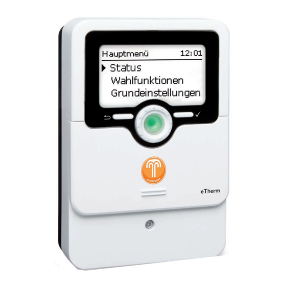
4.1.2 Menüpunkte anwählen und Werte einstellen Im Normalbetrieb des Reglers befindet sich das Display im Statusmenü. Wenn für 1 min keine Taste gedrückt wird, erlischt die Displaybeleuchtung. Nach weiteren 3 min wechselt der Regler in das Statusmenü. Um vom Statusmenü in das Hauptmenü zu gelangen, linke Taste (⟲) drücken! Um die Displaybeleuchtung zu reaktivieren, eine beliebige Taste drücken. - Page 13 Timer einstellen Wenn die Option Timer aktiviert wird, erscheint eine Wochenzeitschaltuhr, mit der Zeitfenster für den Betrieb der Funktion eingestellt werden können. Im Kanal Tageauswahl stehen die Wochentage einzeln oder als häufig gewählte Kombinationen zur Auswahl. Werden mehrere Tage oder Kombinationen ausge- Î...
- Page 14 Zeitfenster kopieren: Zeitfenster ändern: Um bereits eingestellte Zeitfenster für einen weiteren Um ein Zeitfenster zu ändern, folgendermaßen vorgehen: Tag / eine weitere Kombination zu übernehmen, folgen- dermaßen vorgehen: Î Den Tag / die Kombination auswählen, für die Zeitfenster übernommen werden sollen, und Kopieren von anwählen.
-
Page 15: Menüstruktur
Timer zurücksetzen: Menüstruktur Um bereits eingestellte Zeitfenster für einen Tag oder Hauptmenü eine Kombination zurückzusetzen, folgendermaßen Status Regler vorgehen: Regler Zieltemperatur Messteil Minimaltemperatur Î Den gewünschten Tag / die gewünschte Kombina- Wahlfunktionen Hysterese tion auswählen. Grundeinstellungen ∆TEin SD-Karte ∆TAus Handbetrieb …... -
Page 16: Inbetriebnahme
Inbetriebnahme Wenn das System hydraulisch befüllt und betriebsbereit ist, die Netzverbindung des 1. Sprache: Leistungsteils herstellen. Î Die gewünschte Menüsprache einstellen. Der Regler muss über den VBus mit dem Leistungsteil (werkseitig angeschlossen) ® und dem Messteil verbunden sein. Der Regler durchläuft eine Initialisierungsphase, in der das Lightwheel rot leuchtet. -
Page 17: Hauptmenü
Hauptmenü 7. Spülen? Î Gegebenenfalls die Option Spülen aktivieren. Die Spülfunktion dient dazu, das Heizelement zu ent- In diesem Menü können die verschiedenen Menübereiche angewählt werden. lüften. Folgende Menübereiche stehen zur Auswahl: Wenn die Spülfunktion aktiviert wird, wird die Lade- •... -
Page 18: Status
Status 4.5.2 Mess- / Bilanzwerte Im Menü Status / Mess- / Bilanzwerte werden alle aktuellen Messwerte sowie Im Statusmenü des Reglers befinden sich Statusmeldungen zum Regler sowie die verschiedene Bilanzwerte angezeigt. Mess-/Bilanzwerte und Meldungen. Anzeige Bedeutung S1 … S4 Temperatur S1 … S4 S4, S5 Schaltzustand S4, S5 4.5.1 Regler... -
Page 19: Meldungen
4.5.3 Meldungen Menü Regler In diesem Menü können alle Einstellungen für den Hydraulikteil der tubra ® -eTherm Im Menü Status / Meldungen werden Fehler- und Warnmeldungen angezeigt. vorgenommen werden. Im Normalbetrieb wird Alles in Ordnung angezeigt. Die Zieltemperatur und die Rücklaufmaximaltemperatur sind bereits im Inbetrieb- Bei einer Meldung zeigt das Display einen Kurztext zur Art des Fehlers an. -
Page 20: Messteil
Wenn die Temperatur am Rücklaufsensor die eingestellte Rücklaufmaximaltempe- ratur erreicht, wird die Beladung für 15 min gesperrt. Die Sperrzeit wird als Count- down im Statusmenü angezeigt. Der Regler geht wieder in Bereitschaft, wenn die Rücklaufmaximaltemperatur nach Ablauf der Sperrzeit um 2 K unterschritten wird. Die Reserve ist eine einstellbare Überschussleistung, die ins Netz eingespeist und nicht für die Heizung verwendet wird. -
Page 21: Wahlfunktionen
Wahlfunktionen Am Ende jedes Untermenüs zu einer Wahlfunktion stehen die Punkte Funktion und Funktion speichern. Um eine Funktion zu speichern, Funktion speichern auswählen und die Sicher- heitsabfrage mit Ja bestätigen. In bereits gespeicherten Funktionen erscheint an dieser Stelle die Auswahlmöglichkeit Funktion löschen. Um eine gespeicherte Funktion zu löschen, Funktion löschen anwählen und die Sicherheitsabfrage mit Ja bestätigen. - Page 22 Nachheizung intern Nachheizung extern Wahlfunktionen / neue Funktion... / Nachheizung int. Wahlfunktionen / neue Funktion... / Nachheizung ext. Einstellkanal Bedeutung Einstellbereich / Auswahl Werkseinstellung Einstellkanal Bedeutung Einstellbereich / Auswahl Werkseinstellung Tein Einschalttemperatur 20 … 74 °C 40 °C Tein Einschalttemperatur 20 …...
- Page 23 S0 Überschuss S0 Heizung Wahlfunktionen / neue Funktion... / S0 Überschuss Wahlfunktionen / neue Funktion... / S0 Heizung Einstellkanal Bedeutung Einstellbereich / Auswahl Werkseinstellung Einstellkanal Bedeutung Einstellbereich / Auswahl Werkseinstellung Dauer Impulsdauer 30 … 120 ms 100 ms Dauer Impulsdauer 30 …...
- Page 24 Smart Remote Wechselrichter Diese Funktion dient dazu, den Wechselrichter mit reduzierter Leistung zu betrei- ben, wenn der Überschuss einen Schwellwert überschreitet. Der Betrieb wird über ein Schaltsignal vorgegeben. Einstellkanal Bedeutung Einstellbereich / Auswahl Werkseinstellung Leistung Nennleistung Wechselrichter 0,0 … 99,9 kW 0,0 kW Begrenzung Grenze für Schwellwert...
- Page 25 Verbraucher extern Verbraucher extern 2 Diese Funktion dient dazu, einen zusätzlichen externen Verbraucher (z. B. Heizstab, Wenn die Funktion Verbraucher extern aktiviert wurde, wird diese ein zweites Mal Wärmepumpe) einzuschalten, wenn genügend Leistung für dessen Betrieb zur Ver- angeboten (Verbraucher ext. 2). Diese Funktion arbeitet wie Verbraucher extern fügung steht.
-
Page 26: Grundeinstellungen
Grundeinstellungen Folgende Funktionen können mit einer MicroSD-Karte ausgeführt werden: • Mess- und Bilanzwerte aufzeichnen. Nach der Übertragung in einen Computer können die gespeicherten Werte beispielsweise mit einem Tabellenkalkulations- programm geöffnet und visualisiert werden. • Einstellungen und Parametrisierungen auf der MicroSD-Karte sichern und gege- benenfalls wiederherstellen. -
Page 27: Handbetrieb
Hinweis: Unter dem Menüpunkt Alle Relais... können alle Relais gleichzeitig ausgeschaltet (Aus) oder in den Automatikmodus (Auto) gesetzt werden: Die verbleibende Aufzeichnungszeit verringert sich nicht-linear durch die zunehmende Größe der Datenpakete. Die Datenpakete können sich z. B. = Relais ist ausgeschaltet (Handbetrieb) durch den ansteigenden Wert der Betriebsstunden vergrößern. -
Page 28: Bedienercode
4.12 Bedienercode Fehlersuche Tritt ein Störfall ein, wird über das Display des Reglers eine Meldung angezeigt. WARNUNG! Elektrischer Schlag! Bei geöffnetem Gehäuse liegen stromführende Bauteile frei! Î Vor jedem Öffnen des Gehäuses das Gerät allpolig von der Netzspannung trennen! Der Zugriff auf einige Einstellwerte kann über einen Bedienercode eingeschränkt werden (Kunde). - Page 29 Lightwheel ® blinkt rot. F5 A T16 A Sensordefekt. In entsprechendem Sensor-Anzeigekanal wird anstatt einer Temperatur ein Fehlercode angezeigt. Kurzschluss oder Leitungsbruch. Abgeklemmte Temperatursensoren können mit einem Leistungsteil Widerstands-Messgerät überprüft werden und haben bei den entsprechenden Temperaturen die untenste- Das Leistungsteil ist mit einer Sicherung (T16 A) geschützt. Nach Abnahme des Ge- henden Widerstandswerte.
- Page 30 Display ist dauerhaft erloschen. Lightwheel blinkt rot / grün. ® Rechte Taste (✓) drücken. Displaybeleuchtung an? Erscheint im Menü Status / Meldungen die Meldung !VBus Sensormodul? nein nein Regler war im Standby, Die Stromversorgung des Reglers kontrollieren. Ist LED Störung am Messteil blinkt rot? diese unterbrochen? alles in Ordnung nein...
-
Page 31: Index
Index Bedienercode ........................28 Verbraucher extern 2 ......................25 Betriebsmodus, Relais ......................27 Verbraucher extern, Wahlfunktion .................. 25 Bilanzwerte ........................... 18 Wechelrichter, Wahlfunktion .................... 24 Datenaufzeichnung ......................26 Elektrischer Anschluss......................6 Handbetrieb ......................... 27 Inbetriebnahmemenü ......................16 Kontrollleuchte ........................11 Lightwheel ®... - Page 32 Gebr. Tuxhorn GmbH & Co KG Ihr Fachhändler: Senner Str. 171 D - 33659 Bielefeld Tel.: +49 (0) 521 / 44 80 80 Fax: +49 (0) 521 / 44 80 844 www.tuxhorn.de Gebr.Tuxhorn@Tuxhorn.de © Sämtliche Inhalte dieses Dokuments sind urheberrechtlich geschützt.
- Page 33 tubra -eTherm ® per versione 2.01 o superiore Unità di regolazione Manuale per il tecnico qualificato Installazione Comando Funzioni e opzioni Ricerca degli errori Grazie di aver acquistato questo apparecchio. Manuale Leggere attentamente queste istruzioni per poter usufruire al meglio della funzionalità di questo apparecchio. Conservare le istruzioni per riferimenti futuri.
- Page 34 Avvertenze per la sicurezza Destinatari Attenersi scrupolosamente alle presenti avvertenze per la sicurezza per escludere Le presenti istruzioni si rivolgono esclusivamente a personale qualificato e autorizzato. pericoli e danni a persone e materiali. I lavori elettrici devono essere eseguiti esclusivamente da un elettricista specializzato. La prima messa in funzione deve essere eseguita dal costruttore dell’impianto o da una persona qualificata da lui autorizzata.
- Page 35 tubra -eTherm ® tubra -eTherm è un’unità idraulica con regolazione integrata per l’accumulo termi- domestiche. L’unità idraulica compatta è collegabile modularmente all’accumulatore ® co di energia elettrica fotovoltaica per ottimizzare l’autoconsumo. Il misuratore di di acqua sanitaria e al serbatoio tampone. tubra -eTherm può...
- Page 36 tubra -eTherm Dati tecnici modulo di misura ® Ingressi: 3 ingressi di corrente per CT, 3 ingressi di tensione • Aumento dell’autoconsumo fotovoltaico Uscite: 2 uscite impulsi digitali S0 • Riduzione dei costi di riscaldamento e salvaguardia dell’ambiente Alimentazione: 100 – 240 V~ (50… 60 Hz) •...
-
Page 37: Panoramica Del Sistema
Panoramica del sistema Contatore di Sonde Relè energia Temperatura mandata 1 / GND Pompa di carico R1 / N / PE Centralina Temperatura ritorno 2 / GND Riscaldamento integra- R2 / N / PE tivo esterno Temperatura serbatoio 3 / GND utenza esterna 2 Modulo di potenza (opzionale) -
Page 38: Installazione
Installazione Î Eseguire le impostazioni desiderate nel menu Centralina (vedere pagina 19). Collegamento elettrico Montaggio AVVERTENZA! Rischio di scosse elettriche! AVVERTENZA! Rischio di scosse elettriche! Con l’involucro aperto, i componenti conduttori di corrente Con l’involucro aperto, i componenti conduttori di corrente sono esposti! sono esposti! Î... - Page 39 Modulo di misura Cavo VBus per il tubra -eTherm ® ® Comunicazione dati VBus ® Il collegamento avviene con polarità indifferente ai morsetti contrassegnati VBus. Il cavo bus può essere prolungato con un cavo a due conduttori reperibile in com- mercio (filo da campanello).
- Page 40 Collegamento trifasico Collegamento monofase Î Collegare le sonde di corrente e i conduttori del modulo di misura in fase, su- Î Collegare la sonda di corrente e il conduttore L1 del modulo di misura subito bito prima del contatore di energia. La freccia impressa sulle sonde di corrente prima del contatore di energia.
- Page 41 Centralina 100 ... 240 V 100 ... 240 V 50-60 Hz 50-60 Hz DE-33659 Bielefeld DE-33659 Bielefeld tubra -eTherm controller tubra ® -eTherm controller ® IP 20 Made in Germany IP 20 Made in Germany Sensors Sensors R1-R3|1 (1) A 240 V~ R1-R3|1 (1) A 240 V~ L’alimentazione elettrica tramite il modulo di potenza avviene sui morsetti: A1 1...
- Page 42 Modulo di potenza Regler Controller 0-10V T16A 250V~ Netz Mains VBus VBus 1400 W Out1_N Out2_N 800W Out2_L 800 W 1400 W Out1_L F5A 250V~ Out3_L 800W Out3_N 800 W Nota: L’apparecchio deve poter essere staccato dalla rete elettrica in qualsiasi momento.
-
Page 43: Lettore Scheda Microsd Della Centralina
Lettore scheda MicroSD della centralina Comando e funzionamento della centralina La centralina è provvista di un lettore di scheda MicroSD. Tasti e interruttore rotativo Una scheda MicroSD consente di effettuare le seguenti operazioni: • Registrare valori misurati e bilanci su una scheda MicroSD. Una volta trasmessi a un computer, i dati registrati possono essere aperti e visualizzati mediante fogli elettronici. -
Page 44: Selezionare Voci Di Menu E Impostare Valori
4.1.2 Selezionare voci di menu e impostare valori In modalità di funzionamento normale, la centralina mostra il menu Stato. Se non viene premuto alcun tasto per 1 minuto, l'illuminazione del display si spegne. Dopo altri 3 minuti, la centralina passa al menu Stato. Per passare dal menu Stato al menu principale, premere il tasto sinistro (⟲)! Per riaccendere la luce del display, premere un tasto qualsiasi. - Page 45 Impostazione del temporizzatore Attivando l’opzione Temporizz., si visualizza un tem- porizzatore settimanale che permette di impostare delle fasce orarie. Nel canale Selezione giorni si possono selezionare singoli giorni o combinazioni di giorni di frequente se- lezione. Î Per salvare una fascia oraria, selezionare la voce di Se si selezionano vari giorni e/o combinazioni di giorni, menu Salvare e confermare la lettura della do- i giorni e/o le combinazioni selezionate/i vengono rac-...
- Page 46 Copia di fasce orarie: Modifica di fasce orarie: Per applicare una fascia oraria già impostata su un nuo- Per modificare una fascia oraria, procedere come segue: vo giorno e/o una nuova combinazione di giorni, pro- cedere come segue: Î Selezionare il giorno o la combinazione della fascia oraria da copiare, e poi Copiare da.
-
Page 47: Struttura Del Menu
Reimpostazione del temporizzatore: Struttura del menu Per resettare una fascia oraria già impostata per un Menu principale giorno e/o per una combinazione di giorni, procedere Stato Centralina come segue: Centralina Temperatura obiettivo Modulo di misura Temperatura minima Î Selezionare il giorno o la combinazione desiderati. Funzioni opzionali Isteresi Impost. -
Page 48: Messa In Funzione
Messa in funzione Dopo aver riempito l’impianto e quando questo è pronto per il funzionamento, 1. Lingua: allacciare il modulo di potenza alla rete elettrica. Î Impostare la lingua desiderata. La centralina deve essere collegata al modulo di potenza (collegato già in fabbrica) e al modulo di misura tramite il VBus ®... -
Page 49: Menu Principale
Menu principale 7. Risciacquare? Î Se necessario, attivare l’opzione Risciacquare. La funzione risciacquo serve a sfiatare l’elemento ri- Questo menu consente di selezionare vari sottomenu. scaldante. Si hanno a disposizione le seguenti opzioni: Se viene attivata la funzione risciacquo, la pompa di •... -
Page 50: Stato
Stato 4.5.2 Valori / bilanci Nel menu Stato / Valori / bilanci vengono visualizzati tutti i valori attuali rilevati e Il menu Stato della centralina contiene i messaggi di stato sulla centralina e i valori vari valori di bilancio. di misura e di bilancio e i relativi messaggi. Visualizzazione Significato S1 …... -
Page 51: Messaggi
4.5.3 Messaggi Menu Centralina Questo menu consente di effettuare tutte le impostazioni necessarie per il modulo Nel menu Stato / Messaggi vengono visualizzati i messaggi di avvertenza e di errore. idraulico del tubra -eTherm. ® Durante il funzionamento normale, il display visualizza Tutto OK. La temperatura obiettivo e la potenza massima di ritorno sono già... -
Page 52: Modulo Di Misura
La temperatura massima di ritorno funge da valore per la temperatura massima del serbatoio. La centralina passa allo stato Temp. max. (disattivazione massima). La disattivazione massima permette di bloccare il riscaldamento fotovoltaico, per evitare un surriscaldamento del serbatoio che potrebbe causare danni. Se la temperatura rilevata dalla sonda del ritorno raggiunge la temperatura di ri- torno massima impostata, il caricamento viene bloccato per 15 minuti. -
Page 53: Funzioni Opzionali
Funzioni opzionali Alla fine di ogni sottomenu delle funzioni opzionali sono disponibili le opzioni Funz. e Salvare funz. Per salvare una funzione, selezionare Salvare funz. e confermare la domanda di sicurezza con Sì. Nelle funzioni già salvate, in questo punto viene visualizzata l'op- zione Cancellare funz.. - Page 54 Riscaldamento integrativo interno Riscaldamento integrativo esterno Funz. opz. / Nuova funzione... / RI interno Funz. opz. / Nuova funzione... / RI esterno Canale di im- Intervallo di impostazione / Impostazione di Canale di im- Intervallo di impostazione / Impostazione Significato Significato postazione Selezione...
- Page 55 S0 Eccesso S0 Riscaldamento Funz. opz. / Nuova funzione... / S0 Eccesso Funz. opz. / Nuova funzione... / S0 Riscaldamento Canale di im- Intervallo di impostazione / Impostazione Canale di im- Intervallo di impostazione / Impostazione Significato Significato postazione Selezione fabbrica postazione Selezione...
- Page 56 Smart Remote Inverter Questa funzione consente di far funzionare l’inverter a potenza ridotta, se il sur- plus supera una determinata soglia. Il funzionamento viene prestabilito tramite un segnale di commutazione. Canale di im- Intervallo di impostazione / Impostazione Significato postazione Selezione fabbrica Potenza...
- Page 57 Utenza esterna Utenza esterna 2 Questa funzione consente di attivare un’utenza esterna aggiuntiva (per es. riscalda- Se è stata attivata la funzione Utenza esterna, viene offerta una seconda volta (Uten- tore a immersione, pompa di calore), se è disponibile potenza sufficiente per il suo za est.
-
Page 58: Impostazioni Base
Impostazioni base La centralina è provvista di un lettore di schede MicroSD comunemente reperibili in commercio. Una scheda MicroSD consente di effettuare le seguenti operazioni: • Registrare valori misurati e bilanci. Una volta trasmessi a un computer, i dati regi- strati possono essere aperti e visualizzati mediante fogli elettronici. -
Page 59: Modalità Manuale
Nota: Nel menu Mod. manuale è possibile impostare il modo operativo del relè della pompa e degli stadi del modulo di potenza. Il tempo di registrazione residuo diminuisce in modo non lineare, in base all'aumentare della grandezza dei pacchetti di dati. La grandezza dei dati La voce di menu Tutti relè…... -
Page 60: Codice Utente
Nota: Ricerca degli errori Al termine degli interventi di controllo e assistenza tecnica, si deve im- Se si verifica un'anomalia, appaiono dei messaggi sul display della centralina. postare di nuovo la modalità operativa Auto. In modalità manuale non è possibile il funzionamento normale. AVVERTENZA! Rischio di scosse elettriche! Con l’involucro aperto, i componenti conduttori di corrente... - Page 61 Il Lightwheel ® lampeggia di luce rossa. F5 A T16 A Guasto a una sonda. Nel canale di visualizzazione della sonda viene visualizzato un codice di errore invece della temperatura. Rottura del cavo o cortocircuito. Le sonde di temperatura fissate con morsetti possono Modulo di potenza essere controllate con un ohmmetro e hanno la resisti- Il modulo di potenza è...
- Page 62 Il display è permanentemente spento. Il Lightwheel ® lampeggia di luce rossa/verde. Premere il tasto destro (✓). Si accende il display? Nel menu Stato / Messaggi appare il messaggio !VBus Modulo mis.? sì sì La centralina era in Controllare l'alimentazione elettrica della centralina. Il LED Guasto (Error) sul modulo di misura è...
- Page 63 Indice Bilanci ............................. 18 Cambiare il fusibile......................28 Caricare le impostazioni della centralina ............... 27 Codice utente ........................28 Collegamento elettrico ......................6 Dati tecnici ..........................4 Impostazione del temporizzatore ................... 13 Inverter, funzione opzionale ....................24 Lightwheel ® ........................... 11 Menu di messa in funzione ....................
- Page 64 Gebr. Tuxhorn GmbH & Co KG Rivenditore specializzato: Senner Str. 171 D - 33659 Bielefeld Tel.: +49 (0) 521 / 44 80 80 Fax: +49 (0) 521 / 44 80 844 www.tuxhorn.de Gebr.Tuxhorn@Tuxhorn.de © I contenuti di questo documento sono protetti da diritti d'autore.
- Page 65 tubra -eTherm ® beginning with version 2.01 Control unit Manual for the specialised craftsman Installation Operation Functions and options Troubleshooting Thank you for buying this product. Manual Please read this manual carefully to get the best performance from this unit. Please keep this manual safe.
- Page 66 Safety advice Target group Please pay attention to the following safety advice in order to avoid danger and These instructions are exclusively addressed to authorised skilled personnel. damage to people and property. Only qualified electricians are allowed to carry out electrical works. Initial commissioning must be effected by the system installer or qualified personnel named by the system installer.
- Page 67 tubra -eTherm ® tubra -eTherm is a hydraulic unit with an integrated control unit for storing PV the energy meter. In this way, household current priority is ensured by the system. ® current in the form of thermal energy in order to optimise the self-consumption. The compact hydraulic unit can be connected to DHW stores and buffer stores.
- Page 68 tubra -eTherm Technical data measuring unit ® Inputs: 3 current inputs for CT, 3 voltage inputs • Increase in self-consumption of the PV system Outputs: 2 digital S0 impulse outputs • Environmental protection and reduction of heating costs Power supply: 100 … 240 V~ (50 … 60 Hz) •...
-
Page 69: System Overview
System overview Energy Sensors Relay meter Flow temperature 1 / GND Loading pump R1 / N / PE Controller External backup Return temperature 2 / GND R2 / N / PE heating Store temperature 3 / GND External load 2 Power unit (optional) (optional) -
Page 70: Installation
Installation Electrical connection Mounting WARNING! Electric shock! Upon opening the housing, live parts are exposed! WARNING! Electric shock! Î Always disconnect the device from power supply Upon opening the housing, live parts are exposed! before opening the housing! Î Always disconnect the device from power supply before opening the housing! ATTENTION! ESD damage! - Page 71 Measuring unit VBus cable to tubra -eTherm ® ® Data communication VBus ® The connection is to be carried out at the terminals marked VBus (either polarity). The bus cable can be extended with a two-wire cable (bell wire). The cable carries low voltage and must not run together in a cable conduit with cables carrying a S0-1 S0-2...
- Page 72 Three-phase connection Single-phase connection Î Connect the current sensors and the conductors of the measuring unit in Î Connect the current sensor and the conductor L1 of the measuring unit direct- phase directly at the energy meter. The arrow indicated on the current sensors ly at the energy meter.
- Page 73 Controller 100 ... 240 V 100 ... 240 V 50-60 Hz 50-60 Hz DE-33659 Bielefeld DE-33659 Bielefeld tubra ® -eTherm controller tubra ® -eTherm controller Made in Germany IP 20 Made in Germany IP 20 Sensors Sensors R1-R3|1 (1) A 240 V~ R1-R3|1 (1) A 240 V~ The power supply via the power unit is at the terminals: A1 1...
- Page 74 Power unit Regler Controller 0-10V T16A 250V~ Netz Mains VBus VBus 1400 W Out1_N Out2_N 800W Out2_L 800 W Out1_L 1400 W F5A 250V~ Out3_L 800W Out3_N 800 W Note: It must be possible to disconnect the device from the mains at any time. Î...
-
Page 75: Microsd Slot Of The Controller
MicroSD slot of the controller Operation and function of the controller The controller is equipped with a MicroSD card slot. Buttons and adjustment dial With a MicroSD card, the following functions can be carried out: • Store measurement and balance values onto the MicroSD card. After the trans- fer to a computer, the values can be opened and visualised, e.g. -
Page 76: Selecting Menu Points And Adjusting Values
4.1.2 Selecting menu points and adjusting values During normal operation of the controller, the display shows the Status menu. If no button is pressed for 1 min, the display illumination switches off. After 3 more minutes, the controller switches to the Status menu. In order to get from the Status menu into the Main menu, press the left button (⟲)! Press any key to reactivate the display illumination. - Page 77 Adjusting the timer When the Timer option is activated, a timer is in- dicated in which time frames for the function can be adjusted. In the Day selection channel, the days of the week are available individually and as frequently selected combinations.
- Page 78 Copying a time frame: Changing a time frame: In order to copy time frames already adjusted into an- In order to change a time frame, proceed as follows: other day / another combination, proceed as follows: Î Choose the day / the combination into which the time frames are to be copied and select Copy from.
-
Page 79: Menu Structure
Resetting the timer: Menu structure In order to reset time frames adjusted for a certain day Main menu or combination, proceed as follows Status Controller Controller Target temperature Measuring unit Minimum temperature Î Select the desired day or combination. Optional functions Hysteresis Basic settings ∆Ton... -
Page 80: Commissioning
Commissioning When the hydraulic system is filled and ready for operation, connect the power 1. Language: unit to the mains. Î Adjust the desired menu language. The controller has to be connected to the power unit (already connected) and to the measuring unit by means of the VBus ®... -
Page 81: Main Menu
Main menu 7. Flush? Î Activate the flushing option, if necessary. The flushing option is used for venting the heating el- In this menu, different menu areas can be selected. ement. The following menus are available: If the flushing option is activated, the loading pump •... -
Page 82: Status
Status 4.5.2 Measured / Balance values In the Status / Meas. / Balance values menu, all current measurement values as In the Status menu of the controller, controller status messages as well as measure- well as a range of balance values are displayed. ment / balance values and messages can be found. -
Page 83: Messages
4.5.3 Messages Controller menu In this menu, all adjustments for the hydraulic part of the tubra ® -eTherm can be In the Status / Messages menu, error and warning messages are indicated. made. During normal operation, the message Everything OK is indicated. The target temperature and the maximum return temperature have already been A message consists of a short text about the fault condition. -
Page 84: Measuring Unit
If the temperature at the return sensor reaches the adjusted return maximum tem- 10V IN perature, loading is blocked for 15 min. The blocking time is indicated in the status With the 10V IN variant, the power control takes place via an external 0-10 V menu (countdown). -
Page 85: Optional Functions
Optional functions At the end of each optional function submenu, the menu items Function and Save function are available. In order to save a function, select Save function and confirm the security enquiry by selecting Yes. In functions already saved, the menu item Delete function will appear instead. - Page 86 Internal backup heating External backup heating Opt. functions / Add new function / Backup heat.int. Opt. functions / Add new function / Backup heat.ext. Adjustment channel Description Adjustment range / selection Factory setting Adjustment channel Description Adjustment range / selection Factory setting Switch-on temperature 40 °C 20 …...
- Page 87 S0 Excess S0 Heating Opt. functions / Add new function / S0 Excess Opt. functions / Add new function / S0 Heating Adjustment range / se- Adjustment range / se- Adjustment channel Description Adjustment channel Description Factory setting Factory setting lection lection Duration...
- Page 88 Inverter Smart Remote This function is used for operating the inverter at reduced power, if the excess exceeds a threshold. The operation is specified by a switching signal. Adjustment range / Adjustment channel Description Factory setting selection Power Nominal power of the inverter 0.0 … 99.9 kW 0.0 kW Limitation Threshold limit...
- Page 89 External load 2 External load If the external load function has been activated, it is offered a second time This function is used for switching an additional external load (e.g. immersion heat- (Load ext. 2). This function works like External load and is used for switching er, heat pump), if enough power for its operation is available.
-
Page 90: Basic Settings
Basic settings 4.10 MicroSD card SD card In the Basic settings menu, all basic parameters for the controller can be adjusted. Normally, these settings have been made during commissioning. They can be subse- Adjustment channel Description Adjustment range / selection Factory setting quently changed in this menu. -
Page 91: Manual Mode
Note: Note: To safely remove the MicroSD card, always select the menu item Remove The controller will only recognise a firmware update file if it is stored in a folder named ETHERM on the first level of the MicroSD card. card... -
Page 92: User Code
2. Customer 0000 The installer level is not shown, adjustment values can be changed partly. For safety reasons, the user code should generally be set to the customer code before the controller is handed to the customer! Î In order to restrict the access, enter 0000 in the User code menu item. Troubleshooting ATTENTION! Damage by overheating! - Page 93 Lightwheel ® flashes red. F5 A T16 A Sensor fault. An error code instead of a temperature is shown on the sensor display channel. Short circuit or line break. Disconnected temperature sensors can be checked Power unit with an ohmmeter. Please check if the resistance values correspond with the table.
- Page 94 The display is permanently off. Lightwheel flashes red / green. ® Press the right button Is the message !VBus Sensor unit indicated in the Status / Messages menu? (✓) Display illuminated? Controller has been in Check the power supply of the controller. Is it error LED of the measuring unit is flashing red? disconnected? standby, everything OK...
-
Page 95: Index
Index Adjusting the timer ......................13 Lightwheel ® ........................... 11 Balance values ........................18 Manual mode ........................27 Measured values ........................18 Commissioning menu ......................16 MicroSD card ........................ 11, 26 Mounting ..........................6 Control lamp ........................11 Controller adjustments, loading of .................. 27 Operating mode, relays ...................... - Page 96 Gebr. Tuxhorn GmbH & Co KG Distributed by: Senner Str. 171 D - 33659 Bielefeld Tel.: +49 (0) 521 / 44 80 80 Fax: +49 (0) 521 / 44 80 844 www.tuxhorn.de Gebr.Tuxhorn@Tuxhorn.de © All contents of this document are protected by copyright.
- Page 97 DeltaTherm ® Unité de régulation Manuel pour le technicien habilité Installation Commande Fonctions et options Détection de pannes Merci d'avoir acheté ce produit RESOL. Manuel Veuillez lire le présent mode d’emploi attentivement afin de pouvoir utiliser l’appareil de manière optimale. Veuillez conserver ce mode d’emploi.
- Page 98 Recommandations de sécurité Groupe cible Veuillez lire attentivement les recommandations de sécurité suivantes afin d’éviter Ce manuel d‘instructions vise exclusivement les techniciens habilités. tout dommage aux personnes et aux biens. Toute opération électrotechnique doit être effectuée par un technicien en élec- trotechnique.
- Page 99 DeltaTherm ® Le DeltaTherm E est intégré dans la FlowSol E et sert à utiliser l'excédent ® ® de courant PV pour chauffer un réservoir. Un chauffage électrique à 3 niveaux (ré- sistances électriques) chauffe l’eau du réservoir. Cela permet de stocker l'excédent de courant comme chaleur renouvelable.
- Page 100 Caractéristiques techniques module de mesure DeltaTherm ® Entrées : 3 entrées pour CT, 3 entrées tension • Augmentation de l'autoconsommation de l’installation PV Alimentation : 100 … 240 V~ (50 … 60 Hz) • Réduction des coûts de chauffage et diminution de l’impact environ- Type de connexion : Y nemental Standby: <...
-
Page 101: Vue D'ensemble Du Système
Vue d'ensemble du système Compteur Sondes Relais d’énergie Température départ 1 / GND Pompe de charge R1 / N / PE Régulateur Température retour 2 / GND Chauffage d'appoint R2 / N / PE externe (optionnel) Température du réser- 3 / GND Module de puissance voir (optionnelle) Module de mesure... -
Page 102: Installation
Installation Raccordement électrique Montage AVERTISSEMENT ! Choc électrique ! Lorsque le boîtier est ouvert, des composants sous tension AVERTISSEMENT ! Choc électrique ! sont accessibles ! Lorsque le boîtier est ouvert, des composants sous tension Î Débranchez l'appareil du réseau électrique avant sont accessibles ! de l'ouvrir ! Î... - Page 103 Module de mesure Câble VBus ® au DeltaTherm ® Communication de données VBus ® Le VBus se branche sur les bornes VBus (pôles interchangeables). ® Le câble du bus peut se rallonger à l‘aide d‘un câble bifiliaire courant (fil de sonne- rie).
- Page 104 Connexion triphasée Connexion monophasée Î Branchez les sondes de courant et les conducteurs du module de mesure direc- Î Branchez la sonde de courant et le conducteur L1 du module de mesure direc- tement devant le compteur d’énergie en tenant compte des phases. La flèche tement devant le compteur d’énergie.
- Page 105 Module de puissance Régulateur Regler Controller 100 ... 240 V 50-60 Hz T16A 250V~ Netz DeltaTherm ® Mains IP 20 Made in Germany VBus VBus Sensors R1-R2|1 (1) A 240 V~ 1400 W Out1_N Out2_N 800W Out2_L 800 W 1400 W Out1_L F5A 250V~ Out3_L...
-
Page 106: Lecteur De Carte Mémoire Sd Du Régulateur
Lecteur de carte mémoire SD du régulateur Commande et fonctions du régulateur Le régulateur est muni d’un lecteur de carte mémoire MicroSD. Touches et actionneur rotatif Les cartes MicroSD permettent d'effectuer les opérations suivantes : • Enregistrer des valeurs mesurées et des valeurs bilan. Une fois transférées sur un ordinateur, les données enregistrées peuvent être consultées à... -
Page 107: Choix Des Sous-Menus Et Réglage Des Paramètres
4.1.2 Choix des sous-menus et réglage des paramètres En mode de fonctionnement normal, l’écran du régulateur affi che toujours le menu État. Si vous n'appuyez sur aucune touche pendant 1 minute, l'illumination de l'écran s'éteint. Si aucune touche n'est actionnée pendant 3 minutes, le régulateur retourne au menu État. - Page 108 Régler le programmateur Lorsque vous activez l’option Program., un program- mateur hebdomadaire s’affi che sur l’écran et vous permet de défi nir des plages horaires pour la fonction choisie. Le paramètre Sélection jours vous permet de sélec- tionnez individuellement des jours de la semaine ou Î...
- Page 109 Comment copier une plage horaire : Comment modifi er une plage horaire : Pour copier les réglages d'une plage horaire sur un Pour modifi er une plage horaire, effectuez les opéra- autre jour ou combinaison de jours, effectuez les opé- tions suivantes : rations suivantes : Î...
- Page 110 Comment remettre à zéro une plage horaire : Structure du menu Pour remettre à zéro des plages horaires préalable- Menu principal ment défi nies, effectuez les opérations suivantes : État Î Sélectionnez le jour ou la combinaison souhaité(e). Régulateur Régulateur Fonctions optionnelles Température cible Î...
-
Page 111: Mise En Service
Mise en service Dès que le système est rempli et prêt à l’emploi, branchez le module de puissance 1. Langue : sur secteur. Î Sélectionnez la langue de votre choix. Le régulateur doit être connecté au module de puissance (déjà connecté) et au module de mesure à... -
Page 112: Menu Principal
Menu principal 7. Rincer? Î Activez l’option Rincer, le cas échéant. La fonction de rinçage sert à purger l’élément de Ce menu permet de sélectionner le sous-menu de votre choix. chauffage. Les sous-menus disponibles sont les suivants : Lorsque la fonction de rinçage est activée, la pompe de •... -
Page 113: État
État 4.5.2 Mesures / Valeurs bilan Le menu d’état du régulateur indique les messages d’état ainsi que les valeurs de Le menu État / Mesures / Valeurs bilan indique les mesures actuelles ainsi que mesure/bilan et des messages. différentes valeurs bilan . Affi chage Signifi cation S1 …... -
Page 114: Messages
4.5.3 Messages Menu Régulateur Le menu État / Messages indique les messages d’erreur et d’avertissement. Ce menu permet d’effectuer tous les réglages relatifs à la partie hydraulique de la FlowSol En mode de fonctionnement normal, l’écran du régulateur affi che le message Fonc- ®... -
Page 115: Fonctions Optionnelles
La limitation maximale sert à bloquer le chauffage PV afi n d’éviter une surchauffe du réservoir. Lorsque la température mesurée par la sonde retour atteint la valeur maximale, le chauffage s’arrête pendant 15 min. Le temps de blocage s’affi che dans le menu d’état comme compte à... - Page 116 Note : Pour plus d’informations sur le réglage du programmateur, voir page 12. Chauffage d'appoint externe L’option Fonction permet de désactiver ou de réactiver provisoirement les fonc- tions optionnelles préalablement enregistrées. Dans ce cas, les réglages correspon- dants seront sauvegardés et les relais leur ayant été attribués ne pourront pas être attribués à...
-
Page 117: Réglages De Base
Réglages de base Carte mémoire MicroSD Carte mémoire SD Le menu Réglages de base permet de régler tous les paramètres de base du régula- teur. En principe, ces réglages auront déjà été effectués lors de la première mise en Gamme de réglage / Paramètre Signifi cation Réglage d’usine... -
Page 118: Mode Manuel
Note : Comment charger les réglages du régulateur Retirez la carte uniquement lorsque le menu principal s'affi che à nouveau Î Pour charger les réglages du régulateur sur une carte mémoire MicroSD, sélec- sur l'écran après la phase d'initialisation. tionnez l’option Charger réglages. La fenêtre Sélection fi chier s’affi che sur l'écran. -
Page 119: Code D'utilisateur
4.11 Code d'utilisateur Chaque relais peut être réglé individuellement avec le mode de fonctionnement souhaité. Vous pouvez effectuer les réglages suivants : L'accès à certains paramètres est limité et requiert un code d'utilisateur (client). = relais activé à 100 % (mode manuel) 1. -
Page 120: Détection De Pannes
Détection de pannes Wago 2091-1130 Wago 2091-1130 En cas de panne, un message s'affichera sur l'écran du régulateur. AVERTISSE- Choc électrique ! MENT ! Lorsque le boîtier est ouvert, des composants sous tension sont accessibles ! Fusible Î Débranchez l'appareil du réseau électrique avant de l'ouvrir ! Le régulateur est protégé... - Page 121 L'écran est éteint en permanence. Le témoin lumineux de contrôle du Lightwheel clignote en rouge / vert. ® Appuyez sur la touche de droite (✓). L'écran est-il allumé maintenant ? Est-ce que le message !VBus module Sensor? s’affiche dans le menu État / Messages ? Le régulateur était en Vérifiez l'alimentation électrique du régulateur.
-
Page 122: Index
Index Caractéristiques techniques ....................4 Carte mémoire MicroSD ................... 10, 21 Chauffage d’appoint externe, fonction optionnelle ............. 20 Chauffage d’appoint interne, fonction optionnelle ............20 Code d’utilisateur ....................... 23 Comment charger les réglages du régulateur .............. 22 Comment enregistrer les réglages du régulateur ............22 Comment remplacer le fusible .................. - Page 124 RESOL – Elektronische Regelungen GmbH Votre distributeur : Heiskampstraße 10 45527 Hattingen / Germany Tel.: +49 (0) 23 24 / 96 48 - 0 Fax: +49 (0) 23 24 / 96 48 - 755 www.resol.fr contact@resol.fr Le design et les caractéristiques du régulateur sont susceptibles d’être modifiés sans Note importante : préavis.
Need help?
Do you have a question about the tubra-eTherm and is the answer not in the manual?
Questions and answers