Table of Contents
Advertisement
Quick Links
Advertisement
Table of Contents

Related Manuals for SIA SIA-12-L25-CR-TS-4050


Summary of Contents for SIA SIA-12-L25-CR-TS-4050
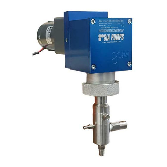
- Page 1 MANUAL INSTALLATION, OPERATION & MAINTENANCE SiA CHEMICAL INJECTION PUMP...
-
Page 2: Illustration & Parts List
ILLUSTRATION & PARTS LIST SIA-12-L25-CR-TS-4050 66.5 M8x1.25 - 6H www.solarinjection.com.au OUT 1/4 - 18 NPT IN 1/4 - 18 NPT MATERIAL TOTAL MASS... - Page 3 ILLUSTRATION & PARTS LIST SIA-12-L25-CR-TS-4050 Item Description Part Number Material DRIVE CASE 40042 6005 T5 MOTOR END PLATE 40044-1 Aluminum-6061 BEARING END PLATE 40047 Aluminum 6061 STROKE LENGTH ASSEMBLY 40084 CRANK SHAFT 15 mm 40045-15 431 SS Bearing 40023 Bearing...
- Page 4 ILLUSTRATION & PARTS LIST SIA-12-L25-CR-TS-4050 Item Description Part Number Material PUMP BODY LOWER 40059 316 SS PUMP BODY MIDDLE 40060 316 SS PUMP BODY UPPER 40061 316 SS O-RING VITON 40067-021 Viton MAIN SEAL UHMWPE 0.250" 40065-1-2 UHMWPE MAIN SEAL TS 0.250"...
-
Page 5: Table Of Contents
2.0 Fuses 2.1 Mounting, Orientation & Environment 2.2 Installation - Step by Step SECTION 3 PUMP OPERATION 3.0 Operating Pump With SiA Timer/Controller 3.1 Chemical Injection Flow Rate Adjustment SECTION 4 MAINTENANCE 4.0 Routine Maintenance: Drive Assembly 4.1 Routine Maintenance: Liquid End 4.2 Routine Maintenance: Gearmotors fitted to the drive... -
Page 6: Section 1 General Description
Lower 1.01 How the Drive Works The SiA Drive Assembly has been designed to give a reliable means of driving a reciprocating chemical injection pump by means of electricity in general, and solar energy in particular. The standard motive force of the Drive Assembly consists of a PMDC, BLDC or A.C. motor driving through an integrally mounted gearbox. -
Page 7: Liquid End
Check Valve Inlet 1.2 Motor & Gearbox A number of motor/gearbox options are available with SiA pumps depending on your application’s requirements. The table below provides an outline of these different options, refer to the Parts List at the front of this manual for part numbers specific to your pump. -
Page 8: Section 2 Installation
SECTION 2 INSTALLATION 2.0 Fuses (PLEASE READ BEFORE INSTALLING) Always ensure the correct fuse is fitted and connections are as per diagrams below to prevent damage to the pump that could void warranty. Always ensure the correct fuse is fitted and connections are as per diagrams below to prevent damage to the pump that could void warranty. -
Page 9: Mounting,Orientation & Environment
We recommend installing the assembly within a weatherproof enclosure. Where this is not practical, ensure as much weather and dust protection is afforded the whole assembly and the motor in particular. An SiA custom cover for the motor and gearbox assembly can be ordered separately if required. -
Page 10: Section 3 Pump Operation
Voltage Recommended Power Voltage Recommended Max. Fuse Rating Max. Fuse Rating (watts) (watts) If the motor power selected requires a fuse greater than 15 amps, SiA recommends the use of a suitable relay that can carry the extra load required. - Page 11 SIAT75001 SiA Smart Controller Revision: TH1 OPERATION First time connection of power (standard software & default settings) It is important to review the default settings (see table below). Please note your controller may have been pre- programmed to your application’s specifications.
- Page 12 SIAT75001 SiA Smart Controller Revision: TH1 OPERATION (cont.) Show Current Settings 1. Depress the ‘+’ & ‘-’ buttons until ‘Show Settings’ appears on the screen. 2. Depress “Select” button to cycle through settings. 3. Depress “Back” to exit. Select Mode 1.
- Page 13 SIAT75001 SiA Smart Controller Revision: TH1 OPERATION (cont.) Power On LCD DISPLAY Indictaes operation Clock When rotating, indicates Controller is running. Battery Status Voltage Full - normal state Half - low power state Empty - power cut state Start Timer Depress ‘Select’...
-
Page 14: Chemical Injection Flow Rate Adjustment
Solar Injection Australia manufactures a range of DC Timers, please contact us or an SiA Distributor for details. -
Page 15: Section 4 Maintenance
WARNING: Should the bearings become worn in any way they should be replaced immediately with new parts available from Solar Injection Australia or SiA Distributors. 6. Place the Crank Shaft and Bearings (or replacement Bearings) into the Drive Case 7. -
Page 16: Routine Maintenance: Liquid End
4.10 Pressure Seal Grease Check main pressure seal grease periodically and refill when necessary. This is done by removing the Lube Plug on the side of the Liquid End and if required, injecting a small quantity of SiA approved grease. -
Page 17: Routine Maintenance: Gearmotors Fitted To The Drive
6. As with the moving internals of the Drive, the operator can expect longer service intervals and life by keeping the gearmotor clean and dry. WARNING: Should the gearmotor show signs of wear in any way it should be replaced immediately with new parts available from Solar Injection Australia or SiA Distributors. -
Page 18: Corrective Maintenance
4.3 Corrective Maintenance Situation Cause Resolution NO PUMP DISCHARGE • Suction &/or discharge check • Clean or replace suction &/or valves not seating discharge check valves • Pump vapour locked • Open bleed plug & prime • Suction or discharge line •... - Page 19 APPENDIX: CHEMICAL COMPATIBILITY CHART Corrosive Agent Steel 304 SS 316 SS C-20 Teflon Viton Buna-N Fluoraz Acetaldehyde Acetate Solvents AceticAcid,20% Acetic Acid Concentrated to l5O°F(66° C) Acetic Acid Concentrated to 2l2°F(100 C ) Acetic Anhydride Acetone Alum Aluminum Chloride Aluminum Nitrate Aluminum Sulfate Ammonia Anhydrous Ammonium Bicarbonate...
- Page 20 CHEMICAL COMPATIBILITY CHART (continued) Corrosive Agent Steel 304 SS 316 SS C-20 Teflon Viton Buna-N Fluoraz Copper Nitrate Copper Sulfate Cottonseed Oil Creosols Cyclohexane Cyclohexanone Dichlorethane, Dry Diethanolamine Diethyl Benzene Diethyl Ether Diethyl Sulfate Diethylene Glycol Dimethyl Amine Dimethyl Phthalate Ether Ethyl Acetate Ethyl Alcohol...
- Page 21 CHEMICAL COMPATIBILITY CHART (continued) Corrosive Agent Steel 304 SS 316 SS C-20 Teflon Viton Buna-N Fluoraz Freons, 80°F(27°C) Fuel Oil Furfural Furfural Alcohol Gallic Acid,5% Gasoline Glucose Glycerine Heptane n-Hexane Hydrazirie,35% and above Hydrobromic Acid Hydrochlodc Acid,37% Hydrocyanic Acid Hydrofluoric Acid to 48% Hydrogen Chloride Dry Hydrogen Cyanide Hydrogen Fluoride-Anhydrous...
- Page 22 CHEMICAL COMPATIBILITY CHART (continued) Corrosive Agent Steel 304 SS 316 SS C-20 Teflon Viton Buna-N Fluoraz Pentane Perfumes Phenol-Molten Phosgene Phosphoric Acid,60 Free of HF Phosphoric Acid, 75% Free of HF Phosphorous-Molten Phosphorous Oxychloride Phosphorous Trichloride Pine Oil Phthalic Anhydride Potassium Chromate Potassium Bromide Potassium Carbonate...
- Page 23 CHEMICAL COMPATIBILITY CHART (continued) Corrosive Agent Steel 304 SS 316 SS C-20 Teflon Viton Buna-N Fluoraz Sulfur-Molten Sulfur Chloride Sulfur Dioxide Dry Sulfan Sulfur Trioxide Sulfuric Acid below 93% Sulfuric Acid-Commercial Concentrated Sulfuric Acid, Fuming, 20% Sulfurous Acid Tannic Acid, 1O% Tartaric Acid Thionyl Chloride Titanium Dioxide Slurry...
- Page 24 Our approach is to innovate rather than imitate. The SiA brand of high quality and highly efficient pumps includes solar-powered; pneumatic/gas; and AC chemical injection pumps that are suitable for a wide range of applications, including hazardous area, sour gas and where other specialist requirements are needed.
Need help?
Do you have a question about the SIA-12-L25-CR-TS-4050 and is the answer not in the manual?
Questions and answers