Table of Contents
Advertisement
Advertisement
Table of Contents

Summary of Contents for GRS BUILD-A-CADE
- Page 1 Instruction Manual tsticks...
-
Page 3: Table Of Contents
CONTENTS Introduction …………………………………….. 2 Safety …………………………………………… 3 Tools ……………………………………………. 4 Parts list ………………………………...……..5 Required parts …………………………………. 7 Assembly instructions ………..….…………..8 Back panel ……………………………………. 19 Operating system installation ………..……. 20 Controls ……….……………………………… 21 System operation ………...…………….….… 21 Playing games ……….…………….………..22 Installing games …………………….…..……... -
Page 4: Introduction
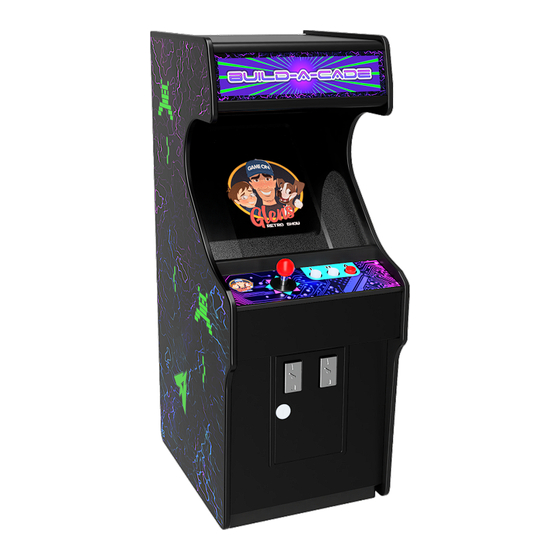
Thank you for purchasing the GRS BUILD-A-CADE 1:6 scale arcade cabinet kit. The BUILD-A-CADE was designed to be as easy to assemble and configure as possible. Using your own Raspberry Pi™ 3 or 4 and power supply, you’ll build a working 1:6 scale arcade machine capable of playing many of your favorite arcade games. -
Page 5: Safety
SAFETY WARNING: Read safety information Please read this entire manual for important safety information about your device. Failure to follow the instructions for proper set up, use, and care for your device can increase the risk of serious personal injury, death, or property damage. -
Page 6: Tools
SAFETY (continued) Do not use your device near heat sources, food, excessive dirt, dust, oil, chemicals, or in strong direct sunlight. Do not place objects on top of your device. Do not insert objects into the vents, ports, or other openings. -
Page 7: Parts List
PARTS LIST SCREEN MOUNT LEFT SIDE RIGHT SIDE CONTROL PANEL FRONT LED PANEL COIN DOOR MARQUEE FRAME CENTER LOWER BRACE MARQUEE FRAME UPPER SCREEN BEZEL BOTTOM... - Page 8 PARTS LIST (continued) CABINET BATTERY ARTWORK STRAP BALL TOP BACK PANEL DUST ASSEMBLY COVER 10MM STAND-OFF (X4) MicroSD EXTENSION 20MM STAND- OFF (X4) SCREEN M2.5x5MM (X4) BATTERY M2.3x6MM (X6) M3x8MM ACRYLIC (X10) MARQUEE M3x8MM SELF ACRYLIC BEZEL TAPPING (X2) 32GB MicroSD RUBBER FOOT CARD with OS (X4)
-
Page 9: Required Parts
PARTS LIST (continued) MAIN WIRE EXTENSION HARNESS USB POWER HDMI CABLE EXTENSION (one each for Pi 3 (Raspberry Pi™ 3 only) and Pi 4) AUDIO CABLE DSI RIBBON CABLE REQUIRED PARTS (Not included) Raspberry Pi™ 4 Raspberry Pi™ 3 Raspberry Pi™ 3 Model B Model B or B+ Model A+... -
Page 10: Assembly Instructions
ASSEMBLY INSTRUCTIONS 1) Unpack all parts and confirm each with the parts list. 2) (optional) Apply ARTWORK (R) to SCREEN BEZEL (F1), ACRYLIC MARQUEE (O) (remove protective film first), LEFT SIDE (A), and RIGHT SIDE (G). Once applied, remove the clear protective film from the artwork. 3) Apply 4 - RUBBER FEET (Q) to the BOTTOM (K1) in their marked positions. - Page 11 ASSEMBLY INSTRUCTIONS (continued) (step 5) 6) With the overhang at the top, secure the SCREEN BEZEL (F1) to the SCREEN MOUNT (F2) USING 4 - M2.3x6mm screws (S4). 7) Insert and tighten 4 - 10mm stand-offs (S1) into the Raspberry Pi™ mounting holes on the back of the SCREEN.
- Page 12 ASSEMBLY INSTRUCTIONS (continued) 8) Gently lift up the latch on the SCREEN DSI connector, insert the DSI RIBBON CABLE (W6) with the blue side facing towards the top, then press down on the latch to secure it in place. blue side latch metal contacts 9) Insert the MicroSD card extension cable (L2) into the...
- Page 13 ASSEMBLY INSTRUCTIONS (continued) 11) Plug all side mounted cables into the Raspberry Pi™; power (W2), HDMI (W5) Pi 3 only, and audio (W3). 12) Attach the WIRING HARNESS (W1) to the GPIO pins of the Raspberry Pi™ with Pin 40 at the bottom right of the header.
- Page 14 ASSEMBLY INSTRUCTIONS (continued) 14) Remove protective film from the both sides of the ACRYLIC MARQUEE (O). Assemble the marquee by placing the BOTTOM MARQUEE CHANNEL (D), TOP MARQUEE CHANNEL (E) and ACRYLIC MARQUEE (O) into position. 15) Plug the 14-pin connector from the WIRING HARNESS into the CONTROL PANEL ASSEMBLY (B).
- Page 15 ASSEMBLY INSTRUCTIONS (continued) 17) Remove the protective film from both sides of the ACRYLIC BEZEL (P), then insert into the slots in the CONTROL PANEL (B) and SCREEN BEZEL (F1) directly in front of the screen. 18) Set the RIGHT SIDE (K) firmly on top of this assembly, making sure all parts set into place.
- Page 16 ASSEMBLY INSTRUCTIONS (continued) 20) Align the BOTTOM (K1) with its tracks, arrow facing front, and slide into place. Stand the assembly upright. 21) Run the 2-pin connector and wires from the WIRING HARNESS through the opening of the LED PANEL (I) and plug into the LED board connector.
- Page 17 ASSEMBLY INSTRUCTIONS (continued) 23) Insert the USB EXTENSION (W4) into the USB port(s) on your Raspberry Pi™. 24) Attach the 8-pin connector from the WIRING HARNESS (W1) to the COIN DOOR (C2) by first running the wire through the front opening of the cabinet. 25) Pull the headphone jack cover out and set the COIN DOOR (C2) into the FRONT (C1), bottom first, then press the top into place while keeping the rubber jack cover...
- Page 18 ASSEMBLY INSTRUCTIONS (continued) 26) Attach the MicroSD card connector to the BACK PANEL (L1) using 2 - M2.3x6mm screws (S4). 27) Attach the HDMI port to the BACK PANEL (L1) using 2 - M3x8mm screws (S5). 28) Plug the AUDIO CABLE (W3) into the audio jack on the circuit board.
- Page 19 ASSEMBLY INSTRUCTIONS (continued) 29) Plug the USB POWER CABLE (W2), main WIRING HARNESS (W1) , and the USB EXTENSION (W4) into the back panel circuit board. Main wiring harness USB power USB extension 30) With the main Power switch OFF, plug the BATTERY into the circuit board.
- Page 20 34) With the power switch OFF, insert the Raspberry Pi™ power adapter (not included) into the USB-C port on the rear of the BUILD-A-CADE cabinet and fully charge the battery (see LED Status below). For best battery performance, remove from power when fully charged.
-
Page 21: Back Panel
BACK PANEL MicroSD card slot Volume control Menu control joystick Soft power button Enter (Y) USB ports Power switch HDMI video output USB-C Power input Status LED... -
Page 22: Operating System Installation
OPERATING SYSTEM INSTALLATION This step requires WiFi internet access. With the power switch in the OFF position, insert the included MicroSD card (T) into the card slot on the back of the BUILD- A-CADE. Turn the unit ON and wait for the installer to initialize. Once the PINN installer initializes, Select your language and keyboard settings from the menu at the bottom of the screen with the joystick or trackball and A button, or USB mouse. -
Page 23: Controls
CONTROLS The included controls are configured for RetroPie, keyboard and MAME as follows. Start RetroPie Left Right 1 2 LeftCtrl Keyboard Start 1 Start 2 B1 MAME Down Select RetroPie Keyboard Coin 1 Coin 2 MAME The two buttons on the back of the cabinet are; Button 1 - Y (Enter), and Button 2 - ESC. -
Page 24: Playing Games
Menu. - Select + B resets the current game. - Select + Start exits the current game. INSTALLING GAMES The BUILD-A-CADE works best with the MAME 0.78 ROM set. Please see retropie.org.uk/docs/Transferring-Roms/ for information on transferring ROMs to your Raspberry Pi™. -
Page 25: Tips
System Options / Network at Boot. ONLINE RESOURCES RetroPie official download retropie.org.uk/download/ RetoPie documentation retropie.org.uk/docs/ Scraping game information (skyscraper is recommended) retropie.org.uk/docs/Scraper/#lars-muldjords-skyscraper The Official GRS Build-A-Cade Users Group facebook.com/groups/buildacade RetroPie setup instructions for Build-A-Cade Pi 3 - thunderstickstudio.com/build-a-cade/Pi3_setup.pdf Pi 4 - thunderstickstudio.com/build-a-cade/Pi4_setup.pdf Sales thunderstickstudio.com... -
Page 26: Pi 4 Notes
PI 4 NOTES If you exit Emulation Station and are in Terminal, either from the Main Menu or by pressing ‘F4’ on a keyboard, the standard way of returning by typing emulationstation will result in the screen being displayed in the wrong orientation. Instead, type arcade to return to Emulation Station. -
Page 27: Optional Control Panels
Optional Control Panels Changing control panels: 1) Remove the 6 screws from the back of the cabinet and then remove the back panel. Keep all wires attached. 2) Slide the bottom back about half way. 3) Slide the center brace back a little until it stops. - Page 28 Optional Control Panels 4) Spread the sides apart slightly and remove the front panel. 5) Slide the control panel to the right to release from the side panel. 6) Pull the control panel out.
- Page 29 Optional Control Panels 7) Unplug the wiring harness(es) from the control panel. 8) Plug the wiring harness(es) into the new control panel. For the spinner and trackball panels, insert the included USB cable into an available port on the Pi. Keep the cable above the center brace.
- Page 30 Optional Control Panels 11) Insert the front panel. 12) Slide the bottom and center brace into place. 13) Replace the 6 screws to reinstall the back panel.
- Page 31 Optional Control Panels Control panel use: The default button layout for each control panel is shown here. RetroPie MAME left_ctrl Start P1 Start left right J P2 Start down Btn 1 Dual Joystick unassigned Btn 2 unassigned Btn 3 left_ctrl space left_alt Left...
-
Page 32: Spinner/Trackball Notes
SPINNER/TRACKBALL NOTES If the spinner or trackball do not respond and you have another mouse device attached, apply Spinner/Trackball Fix in the Options menu. This script changes Port 1 Mouse Index from 0 to 1 in RetroArch input settings. Spinner/Trackball Reset will restore the default settings. Spinner and trackball sensitivity settings should be set in each game. -
Page 33: Notes
NOTES If you exit Emulation Station and don't have a keyboard to return, press the joystick up once or until either "emulationstation" (Pi 3) or "arcade" (Pi 4) appears and then press rear button 1. The joystick is used to scroll through the commands entered in the terminal. - Page 34 NOTES...
- Page 36 Designed by:...
Need help?
Do you have a question about the BUILD-A-CADE and is the answer not in the manual?
Questions and answers