
Summary of Contents for RTL INSTABOOM LITE
- Page 1 INSTABOOM LITE Mobile Barrier Gate PLEASE READ ALL INSTRUCTIONS CAREFULLY BEFORE PROCEEDING WITH THE INSTALLATION Version 1.0 05 August 2022 1 0800 785 744 rtl.co.nz ...
-
Page 2: Table Of Contents
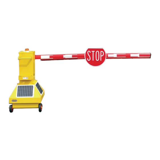
Re‐Assembly Instructions: ........................ 3 User Guide: .............................. 5 Safety Features: ............................ 7 Charging: .............................. 8 Recovery from Low Voltage: ........................ 9 Pairing Remote Fobs: .......................... 10 Replacing Remote Fob Batteries: ...................... 11 Telematics Portal: .......................... 12 Product Introduction: The Instaboom Lite Portable Barrier Gate is a lightweight, solar powered barrier arm, suited to short duration traffic management of major projects and construction sites. Having a physical barrier arm provides instant demarcation for your worksite. The Lite Barrier is only 48kgs so can be manually offloaded by two people and set up in minutes. Always check the www.rtl.co.nz for new versions of this installation manual – Search Instaboom Barrier Component List: This component list is one for one Instaboom Barrier ‐ one side of the road. 1x mobile barrier (branded) 1x Barrier wheel‐barrow handle 3x boom sections 1x 4 button remote fob ... -
Page 3: Re-Assembly Instructions
Re‐Assembly Instructions: After unpacking your INSTABOOM Lite from the packing case, the boom mount will need re‐ orientation before it can be used. Unpacking state For packing only the boom has been oriented downwards. Remove Boom and cup assembly Note the position of the boom on the square plate. Once removed, the boom should be re‐ fitted into the same holes. Undo the four bolts holding the boom cup to the plate. You will need a 13mm spanner and 13mm socket. 3 ... - Page 4 ` Re‐affix the boom mount Re‐fix the boom mount onto the square plate with the boom oriented upwards. Securely tighten the bolts through the same holes used previously. Fit the finger guard Remove the two screws from the square plate. Slide the finger guard over the top of the now vertical boom. Position it over the square plate, lining it up with screw holes. Fit securing screws Locate one of the securing screws into its hole. Squeeze the finger guard so you can see the other screw hole and locate the second screw into position. Tighten both screws. ...
-
Page 5: User Guide
User Guide: Normal Operation Position Manoeuvre the INSTABOOM into place on firm level ground using the handle supplied. Remove the handle. Assemble the boom Remove the three boom sections from the rear storage area and assemble them to form the boom arm. The pieces slot together and click into place with spring clips. Fit the boom to the INSTABOOM Using two hands, position the boom onto the mount on the INSTABOOM. Support the boom with one hand while compressing the spring clip with the other and the boom assembly will slot into place ... - Page 6 Switch the INSTABOOM on Switch the INSTABOOM on using the two position switch Check the charge level The USB charge port can be used to charge USB devices such as your mobile phone. You can press the button to view the current charge state of the INSTABOOM. Once the charge reaches 11.9v please follow the procedure below to charge your barrier from a local mains supply. Move the barrier Depress the button on the fob which corresponds to the INSTABOOM you have selected. The barrier will come down. Click the same button again to send it up to the vertical position. The barrier works on a “push to open, push to close” basis. It is possible to programme a barrier to each of the buttons on the remote fob. Please see guide below for a guide on this process. ...
-
Page 7: Safety Features
Safety Features: Non‐contact safety The INSTABOOM Lite is equipped with a Class 1 laser sensor to scan the area under the boom to prevent the barrier coming down and striking objects or people. If an object interrupts the laser beam in an area between 300mm and 3000mm in a direct line out from the laser window, the barrier will not come down. If an object is detected while the barrier is moving to come down, it will reverse direction and return to the vertical. Contact safety If the boom does come into contact with an otherwise undetected object while moving to the horizontal position, it will detect this and reverse direction, returning to the vertical. ... -
Page 8: Charging
Charging: Operational voltage Your INSTABOOM Lite is a 12v system designed to be solar/hybrid. This means that, while it is equipped with 40w of solar, it will require periodic charging dependent on use. You can use the USB charger output to check the voltage of your INSTABOOM. Once below 11.9v it will require charging. Connect the charger Your INSTABOOM Lite was shipped with a separate mains charger. Connect the charger output cable to the Anderson socket on the side of the barrier. Then connect the mains cable to your local mains outlet (110‐240v AC). Charge the INSTABOOM Switch the charger on and allow the INSTABOOM to charge for at least 12 hours. The charger is a trickle charger and a 24 hour charge is the best way to condition your batteries. ... -
Page 9: Recovery From Low Voltage 1
Recovery from Low Voltage: Recovery from low voltage 1 If the INSTABOOM is allowed to drop below operational voltage, the solar charge regulator will cut off power to the control board to allow the device to recharge from solar. In this eventuality you will need to switch on the device manually. To do this, remove the cover from the top turret by unscrewing the 6 retaining screws Recovery from low voltage 2 Withdraw the cover. If the LOAD light is not illuminated, click the black button once to re‐ enable the INSTABOOM. ... -
Page 10: Pairing Remote Fobs
Pairing Remote Fobs: Unscrew the whip antenna and remove the device from the green boot The arrows show the activation point of each device. This is required for the next step. Remove the cover from the top turret by unscrewing the 6 retaining screws Touch the bottom left of the transmitter against the top left of the receiver for 1 second, as shown. The receiver will beep once. Press the chosen number switch on the transmitter you wish to pair. The receiver will beep twice to confirm pairing. Additional The receiver can store up to 30 transmitter pairings so when a barrier returns to base it is good practise to erase all fob pairings from its memory to prevent unwanted operation. To achieve this, touch the bottom left of the transmitter against the top left of the receiver, as described above, but hold it in position for over 5 seconds. The receiver will emit a long beep to confirm all pairings have been erased. You will then need to follow the steps above to pair a new remote fob. ... -
Page 11: Replacing Remote Fob Batteries
Replacing Remote Fob Batteries: Unscrew the whip antenna and remove the device from the green boot Remove the six case screws with a small Philips screwdriver Open the case and remove the two black Philips screws from the battery case Exchange the three AAA batteries and reassemble the handset by reversing this process ... -
Page 12: Telematics Portal
Telematics Portal: Navigate to www.solargates.co.uk/instaboom/login And click on the “Tracker log in” link Log in with your User name and Password credentials User name: CONTACT RTL Password: CONTACT RTL Items of plant are shown on the left hand side. GPS positions are shown on the map panel. The top panel shows the feed of status updates, in order of occurrence. User the side panel to search for a specific item of plant. This icon depicts the state of the boom – either up or down. ... - Page 13 This icon depicts whether the item of plant is being transported. This icon depicts the power state of the barrier. Green is ON and red is OFF. Click the triangle to focus the map on the GPS position of this item of plant. The barriers are shown as green dots on the map. Click on them to bring up the dashboard of telemetry recorded on the that barrier, shown in the next step. This is the unit dashboard, allowing you to see all the current readouts from an individual device. It is possible to set up notifications based on triggers such as battery voltage or movements into or out of custom geofences. Please contact us at Solar Gates for assistance with this. Please send photos through to marketing@rtl.co.nz ...
Need help?
Do you have a question about the INSTABOOM LITE and is the answer not in the manual?
Questions and answers