Table of Contents
Advertisement
Quick Links
Advertisement
Table of Contents

Summary of Contents for DKK-TOA NHMS-4
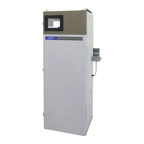
- Page 1 AMMONIUM ION MONITOR MODEL NHMS-4 Please keep this instruction manual close at hand of the persons who are in charge of the operation of this product. Before operating this product, please read this instruction manual carefully for its correct handling.
- Page 2 Introduction Introduction (a) Thank you for your purchase of Ammonium Ion Monitor Model NHMS-4. The Model NHMS-4 Ammonium Ion Monitor (hereinafter referred to as the equipment or product) can continuously measure the ammonium ion concentration in the sample water. This product is used for water quality management of each process, effluent monitoring, and water quality monitoring of rivers and lakes.
-
Page 3: Safety Information
Model: NHMS-4 Safety Information Safety Information (1) Meaning of markings The signal terminology and symbols related to warnings in the instruction manual are defined below. The alert symbol mark ( : General caution mark) indicates the possibility of hazard or damage and also means “Refer to the instruction manual.”... -
Page 4: Safety Compliance Items
Model: NHMS-4 Safety Information (2) Safety compliance items Hazardous Materials The following solutions to be used are hazardous materials. Always check the Material Safety Data Sheet (MSDS) and wear protective gear when handling them. • Reagent (20 w/v% sodium hydroxide solution) •... - Page 5 (d) The contents of the manual may be changed without prior notice for reasons such as to improve performance. (e) Intellectual property right of the manual belongs to DKK-TOA. All or part of the manual must not be reproduced without permission.
- Page 6 (h) Loss of data, settings, programs, or software stored on the product not attributable to DKK-TOA. (i) Any product other than DKK-TOA’s, if specified by the purchaser or user, that incorporates, or is incorporated into or combined with DKK-TOA’s products (*1). In such cases, this warranty covers DKK-TOA’s products only.
-
Page 7: Reading Guide
Model: NHMS-4 Reading Guide Reading Guide Refer to the necessary sections of this instruction manual depending on your purposes such as understanding the outline of this product or starting the product as shown below. The numbers in circles indicate sections to be referred to in sequential order. -
Page 8: Table Of Contents
Model: NHMS-4 Table of Contents Table of Contents ●Introduction ······················································································· 1 ●Safety Information ········································································· 2 (1) Meaning of markings 2 (2) Safety compliance items 3 (3) Notes on use of the instruction manual 3 ●Warranty ···························································································· 5 ●Reading Guide... - Page 9 Model: NHMS-4 Table of Contents (1) External input/output list 43 (2) External contacts output and loop check 45 (3) External start and loop check 45 (4) Transmission output and loop check 46 (5) Digital input/output and loop check 46 3.5 Operation Stop ·················································································...
- Page 10 Model: NHMS-4 Table of Contents (16) Calibration order check 109 (17) Device address change 109 (18) Security set and clear 111 (19) Reagent flow check 114 (20) Alarm value change 115 (21) Dead zone change 117 (22) Sample water off alarm transmission switching ...
- Page 11 Model: NHMS-4 Table of Contents (1-1) Measurement stop and ion electrode removal 179 (1-2) Ion electrode assembling and measurement restart 180 (2) Measuring cell cleaning 181 (3) Membrane and internal solution replacement 182 (4) Ion electrode replacement 183 (5) Stirring motor replacement ...
- Page 12 Model: NHMS-4 Table of Contents (2) Flow sheet 217 (3) Time chart 218 9. Installation ··················································································· 225 9.1 Installation Example ········································································ 225 9.2 Installation Conditions ····································································· 227 (1) Sample water sampling point conditions 227 (2) Installation site conditions 227 9.3 Installation ····················································································...
-
Page 13: Configuration And Part Names
Model: NHMS-4 1.1 Configuration Example and Specifications Check 1. Configuration and Part Names 1.1 Configuration Example and Specifications Check Ion monitor Waste solution tank Pump (option) Configuration Example of Ammonium Ion Automatic Measurement (a) This equipment can quantify the ammonium ion concentration by adding a reagent (sodium hydroxide solution) to the sample and measuring the electric potential with an ammonium ion electrode (hereinafter referred to as “ion electrode”) as the indicating electrode. - Page 14 Model: NHMS-4 1.1 Configuration Example and Specifications Check Communication start Operation by communication function (RS-485). Operation is almost the same as external starting. • Continuous measurement and intermittent measurement 1 method can be selected from among the followings: Intermittent measurement ...
-
Page 15: Name Of Each Part
Model: NHMS-4 1.2 Name of Each Part 1.2 Name of Each Part Recorder (option) <Appearance> Operation panel (controller) Power switch (earth leakage breaker) Power lamp USB interface USB memory Reagent pump Detector section Sample water pump Mixing chamber Air pump (option –... - Page 16 Model: NHMS-4 1.2 Name of Each Part External connection terminals Piping port (option) Waste solution tank outlet (option) Measurement cell outlet Pre-treatment tank outlet Wash water inlet Sample water inlet Pan outlet Name of Main Parts on the Right Side...
-
Page 17: Operation Panel
Model: NHMS-4 1.3 Operation Panel 1.3 Operation Panel (a) Operation panel function outline The operation panel is a graphic type touch panel. Screen switching and parameters settings, which are the operation conditions, can be changed by touching the operation key according to the purpose such as automatic operation, maintenance, etc. -
Page 18: Operation Screens Map
Model: NHMS-4 1.4 Operation Screens Map 1.4 Operation Screens Map (Power ON) >> 4.1 "Measurement Screen Operation" "Automatic "KEY LOCK", "ALARM", "MAINT OUT", "MONITOR" and "USB" have measurement ・ the same function as "MEAS(MEAS STOP)" screen. start" dialog box "PARAMETER" has the same function as "MEAS(MEAS ・... -
Page 19: Preparation For Operation
Model: NHMS-4 2.1 Ion Electrode Installation 2. Preparation for Operation This chapter explains the operations that are performed before power is supplied to the equipment. If power is being supplied to the equipment, turn off the power at the supply source. - Page 20 Model: NHMS-4 2.1 Ion Electrode Installation 【IMPORTANT】 Do not touch the membrane at the ion electrode end with your hands. If the membrane is dirty or damaged, membrane and the internal solution must be replaced. If the membrane is scratched or otherwise abnormal, replace the membrane and internal solution before installing the ion electrode.
- Page 21 Model: NHMS-4 2.1 Ion Electrode Installation ⑥ Install the detector section cover. Return the detector section cover to its original state and tighten it securely with the butterfly bolt. 【IMPORTANT】 If the cover is loose, air may enter the detector section and condense on the aluminum block and cause trouble.
-
Page 22: Solution Preparation And Filling
Model: NHMS-4 2.2 Solution Preparation and Filling 2.2 Solution Preparation and Filling (1) Solution type (a) The following tanks must be filled with each solution. Solution Type Solution Tank and capacity Remarks Reagent Reagent tank (10 L) 20 w/v% sodium hydroxide solution... -
Page 23: Filling Of Acid Washing Solution
Model: NHMS-4 2.2 Solution Preparation and Filling ② Fill the reagent tank. Remove the reagent tank from the equipment and remove the cover with tube, after checking that the tank is empty, fill the tank with 10L of reagent. -
Page 24: Preparing The Acid Washing Solution
Model: NHMS-4 2.2 Solution Preparation and Filling 【IMPORTANT】 The acid washing solution is corrosive. If it spills into or around the equipment, immediately wipe it off and thoroughly clean with city water, etc. ① Prepare the acid washing solution. Prepare the accessory acid washing solution. -
Page 25: Preparation And Filling Of Hi Calibration Solution
Model: NHMS-4 2.2 Solution Preparation and Filling Measuring Range and Standard Calibration Solution Concentrations Standard calibration solution Transmission output range concentration (NH Measuring range of equipment (NH Transmission Transmission LO calibration HI calibration zero (4 mA) span (20 mA) solution solution 0.05 to 5.00 mg/L (standard) - Page 26 Model: NHMS-4 2.2 Solution Preparation and Filling Hazardous Materials ● The ammonium ion standard solution used is toxic. Always check the Material Safety Data Sheet (MSDS) and wear protective gear when handling them . ● Do not mix the ammonium ion standard solution and each calibration solution with an alkaline solution.
-
Page 27: Preparation And Filling Of Lo Calibration Solution
Model: NHMS-4 2.2 Solution Preparation and Filling (4-3) Preparation and filling of LO calibration solution LO calibration solution tank LO Calibration Solution Tank (5 L) Since the equipment sends the LO calibration solution to the cell in preparation for the next measurement after acid washing, fill the tank with LO calibration solution even when measurements are made without performing calibration. -
Page 28: Preparation Of Ll Calibration Solution
Model: NHMS-4 2.2 Solution Preparation and Filling ③ Check the standard solution collecting amount. Check the collecting amount of the ammonium ion standard solution (1000 mg/L) matched to the LO calibration solution concentration and preparation amount by the following table. -
Page 29: Preparing The Ammonium Ion Standard Solution
Model: NHMS-4 2.2 Solution Preparation and Filling (4-5) Preparing the ammonium ion standard solution The ammonium ion standard solution (1000 mg/L) can be prepared by the following procedure. Hazardous Materials ● The ACS grade ammonium chloride used and the ammonium ion standard solution prepared are toxic. -
Page 30: Operation
Model: NHMS-4 3.1 Test Run and Adjustment Procedure 3. Operation 3.1 Test Run and Adjustment Procedure Perform normal measurement by performing test run and adjustment as follows: ① Check the installation. Before running; check that installation work (installation, piping, and wiring) is complete. - Page 31 Model: NHMS-4 3.1 Test Run and Adjustment Procedure Introduce the sample water into the pre-treatment tank. Sample water inlet Valve BV2 (wash water) Valve BV1 (sample water) Waste solution tank outlet (option) Measurement cell outlet Pre-treatment tank outlet Wash water inlet Pan outlet <Front>...
- Page 32 Model: NHMS-4 3.1 Test Run and Adjustment Procedure ⑧ Test the earth leakage breaker. The earth leakage breaker switch also serves as the equipment power switch. ⓐ Check that the power lamp (POWER) is off, and turn on the power switch (ON, up position).
- Page 33 Model: NHMS-4 3.1 Test Run and Adjustment Procedure 2012/02/08 10:31 [WASH RECOVERY] Under recovery. Please wait for a while. STOP Handled by 1-sec pressing “WASH RECOVERY” Screen The “WASH RECOVERY” screen is displayed when the power is turned on after the power was turned off by a power interruption or by mistake during acid washing.
- Page 34 Model: NHMS-4 3.1 Test Run and Adjustment Procedure 2012/02/08 10:31 [MEAS] KEY LOCK ALARM MAINT OUT 0. 15 ANMONIUM m g / L START STATUS Prepration /STOP PROCESS SAMPLE SEND REMAINED TIME 55. 2 POTENTIAL SENSITIVITY % CELL TEMP 25. 0 ℃...
- Page 35 Model: NHMS-4 3.1 Test Run and Adjustment Procedure The parameters can be checked even during measurement, but to make changes, measurement must be stopped. [Measuring range and calibration solution concentration] Make “TRANS ZERO” and “TRANS SPAN” suitable for the measuring range. >> 4.3(29) “Transmission output range check and change”...
-
Page 36: Operation Method Selection
Model: NHMS-4 3.2 Operation Method Selection 3.2 Operation Method Selection (1) Starting method selection (a) Select internal start, external start, or communication state of the following table and switch the parameter settings according to the reference item. (b) For internal start, also check “NEXT WASH TIME”, etc. based on the following table. For external start, wire so that “MEAS START”... - Page 37 Model: NHMS-4 3.2 Operation Method Selection 【IMPORTANT】 When the intermittent measurement start time is the same as the next wash time or the next calibration time, calibration is given priority and intermittent measurement is not performed. (c) The intermittent measurement interval is effective not only for internal start, but also when intermittent measurement is performed by external start and communication start.
-
Page 38: Calibration Method Selection
Model: NHMS-4 3.3 Calibration Method Selection 3.3 Calibration Method Selection (1) Times when the calibration is necessary Calibration is a function which corrects the concentration conversion formula. This equipment requires calibration by LO calibration solution and HI calibration solution at the following times: (a) At test run and adjustment ... - Page 39 Model: NHMS-4 3.3 Calibration Method Selection (Continued from previous page) Overview When calibration is started by screen operation, the (Continued) Manual read HI Manual calibration equipment starts HI calibration solution measurement. When calibration [CAL OPE] is touched after the indication stabilizes, the equipment executes span calibration.
-
Page 40: Automatic Calibration Setting
Model: NHMS-4 3.3 Calibration Method Selection (c) The automatic calibration function is different depending on the starting method. Refer to 3.2(1) “Starting method selection” and perform the necessary settings. (d) Manual calibration is calibration performed while measurement is stopped. Perform it by referring to the relevant items, as required. -
Page 41: Acas Calibration Function
Model: NHMS-4 3.3 Calibration Method Selection (Continued from previous page) Function Parameter setting, others Reference item At normal calibration, if the electrode sensitivity (5) Make “LO CAL CONCENT” 4.3(26) “Calibration is under 20%, an electrode sensitivity alarm and and “HI CAL CONCENT” the solution concentration calibration alarm are transmitted. - Page 42 Model: NHMS-4 3.3 Calibration Method Selection (c) ACAS calibration cannot be selected with external start and communication start. The calibration mode becomes normal calibration. Measurement start Measurement When getting to the time for calibration Calibration SLOPE etc. diagnosis Electrode sensitivity 50% or less...
- Page 43 Model: NHMS-4 3.3 Calibration Method Selection Electrode potential stability EMF stability of HI calibration solution Response Response of HI calibration solution Electrode potential change SLOPE Self-diagnosis based on Electrode sensitivity (%) our field experience Next calibration time setting...
-
Page 44: External Input/Output And Loop Check
Model: NHMS-4 3.4 External Input/output and Loop Check 3.4 External Input/output and Loop Check (1) External input/output list (a) The following signals can be input and output through the external input/output terminals of the equipment. Refer to 3.4(2) “External contacts output and loop check” 3.4(5) “Digital input/output and loop check”... - Page 45 Model: NHMS-4 3.4 External Input/output and Loop Check (Continued from previous page) Terminal No. Name (abbreviation, display) Operation contents No-voltage contact input, ON resistancewithin 50 Ω, External contact input short-circuit currentmax. 10 mA, open voltage24 This signal causes equipment in the automatic...
-
Page 46: External Contacts Output And Loop Check
Model: NHMS-4 3.4 External Input/output and Loop Check (2) External contacts output and loop check (a) At the start of operation, refer to 4.4(6) “External contact output check” and perform external contract output signal loop check. This operation checks that the external contact output signals operate appropriately. -
Page 47: Transmission Output And Loop Check
Model: NHMS-4 3.4 External Input/output and Loop Check (d) Continuous/intermittent switching signal This signal is not a pulse closed contact signal but is an open/closed contact signal. When terminals 58-59 are “Open” and a measurement start input signal (pulse closed contact) is input, continuous measurement starts. When terminals 58-59 are “Closed”, intermittent measurement starts. -
Page 48: Operation Stop
Model: NHMS-4 3.5 Operation Stop 3.5 Operation Stop (a) If the equipment is stopped for a long time, the reagents remaining inside the equipment may precipitate. For this reason, the operation stop procedure is different depending on the period operation is to be stopped. - Page 49 Model: NHMS-4 3.5 Operation Stop Hazardous Materials The solution in reagent tank and acid washing solution tank are toxic. Always check the Material Safety Data Sheet (MSDS) and wear protective gear when handling them. Do not mix the calibration solution in each calibration solution tank with the alkaline solution.
- Page 50 Model: NHMS-4 3.5 Operation Stop Solenoid valve (SV3) Sample water Pre-treatment tube( φ 3× φ2) tank cover Sample water tube Sleeve Pre- treatment- tank Sleeve Valve BV1 Tank with pure Filter body water Sample water filter Cap nut Sample Water Tube and Pre-treatment Tank Cover ⑤...
- Page 51 Model: NHMS-4 3.5 Operation Stop ⑧ Return the sample water tube to its original state. Pass the sample water tube through the pre-treatment tank cover and connect the sample water filter and return the tube to the pre-treatment tank.
- Page 52 Model: NHMS-4 3.5 Operation Stop ⑭ Reinstall the detector cover Return the removed detector cover to its original state. ⑮ Close other valves. In addition, if there is a valve provided outside the equipment, close it. ⑯ Turn off the power. Set the power switch to OFF.
-
Page 53: Modes Of Operations
Model: NHMS-4 4.1 Measurement Screen Operation 4. Modes of Operations 4.1 Measurement Screen Operation (1) Measurement screen functions (a) Functions of measurement screens and keys The “MEAS (MEAS STOP)” screen is the basic screen. When the power switch is turned ON, this screen appears. Measurement start, switching to the “MAINT”... - Page 54 Model: NHMS-4 4.1 Measurement Screen Operation Measurement Screen Keys and Displays Name and notation in text Function and display contents When “MEAS (MEAS STOP)” screen is displayed When touched it, an Start/Stop key “Automatic measurement start” dialog box opens. >> 4.1(2) “Automatic [START/STOP] measurement start”...
- Page 55 Model: NHMS-4 4.1 Measurement Screen Operation (Continued from previous page) Name and notation in text Function and display contents When touched, the “CF/USB REMOVAL” screen is displayed and when USB key touched for more than 1 second at [USB REMOVAL] of that screen, the [USB] equipment enters the “USB REMOVAL OK”...
- Page 56 Model: NHMS-4 4.1 Measurement Screen Operation 2012/02/08 10:31 2012/02/08 10:31 [EX START] [EX START] ALARM ALARM 0. 15 m g / ----- ANMONIUM ANMONIUM m g / L MEAS IN START STATUS STATUS Prepration ーーーーーーーー PROCESS PROCESS WAIT SAMPLE SEND...
- Page 57 Model: NHMS-4 4.1 Measurement Screen Operation Display and Output by Operation Status Modbus Measurement screen High/low alarm Transmission output communication and concentration display output USB memory log data Measurement stop “---” displayed Transmission mode None *2 None format Measurement Instantaneous...
-
Page 58: Automatic Measurement Start
Model: NHMS-4 4.1 Measurement Screen Operation (2) Automatic measurement start (a) Automatic measurement can be started by “MEAS (MEAS STOP)” screen key operation. Touch [START/STOP] while the equipment is stopped. “Automatic measurement start” dialog box opens. 【IMPORTANT】 Always perform this operation at the “MEAS (MEAS STOP)” screen. If “Yes”... -
Page 59: Automatic Measurement Stop
Model: NHMS-4 4.1 Measurement Screen Operation (Continued from previous page) Step and operation Screen example ④ Check that the “MEAS (MEAS)” screen is 2012/02/08 10:31 displayed. Check that “MEAS” is displayed at the [MEAS] KEY LOCK ALARM MAINT OUT top left-hand corner of the screen. -
Page 60: Key Lock Switching
Model: NHMS-4 4.1 Measurement Screen Operation (Continued from previous page) Step and operation Screen example ③ Stop automatic measurement. Touch [Yes] in 2012/02/08 10:31 the “Automatic measurement stop” dialog box. [MEAS] KEY LOCK ALARM MAINT OUT Automatic measurement stops and the dialog box 0. -
Page 61: Alarm Check And Clear
Model: NHMS-4 4.1 Measurement Screen Operation Key Lock Switching Operation Step and operation Screen example ① Check that [KEY LOCK] is displayed on the 2012/02/08 10:31 screen. Check that the “MEAS (MEAS)” or other [MEAS] KEY LOCK ALARM MAINT OUT screen with [KEY LOCK] is displayed. - Page 62 Model: NHMS-4 4.1 Measurement Screen Operation Alarm transmission date Alarm item symbol Higher limit alarm 12/02/07 18:09:08 ALM HH High limit alarm 12/02/07 17:58:44 ALM H 12/02/07 10:05:32 AL2 SAMPLE Sample water off error ALARM CLEAR key Cleared by 3-sec pressing ALARM CLEAR (Touch for 3 seconds or more.)
-
Page 63: Maintenance In Progress" Signal Switching
Model: NHMS-4 4.1 Measurement Screen Operation Alarm Check and Clear Operation Step and operation Screen example ① Display a screen with [ALARM] on it. Display 2012/02/08 10:31 the “MEAS (MEAS)” screen or other screen with [MEAS] KEY LOCK ALARM MAINT OUT [ALARM] on it. - Page 64 Model: NHMS-4 4.1 Measurement Screen Operation “Maintenance in progress” Signal Switching Operation Step and operation Screen example ① Check that [MAINT OUT] is displayed on the 2012/02/08 10:31 screen. Check that the “MEAS (MEAS STOP)” or [MEAS] KEY LOCK...
-
Page 65: Liquid Level Check Of Tanks By Monitor
Model: NHMS-4 4.1 Measurement Screen Operation (7) Liquid level check of tanks by monitor (a) The liquid level of the LO calibration solution tank and other tanks can be checked by “Monitor” dialog box opened by touching [MONITOR]. (b) The result of judgment of the liquid level by float switch of each tank is displayed in the “Monitor”... -
Page 66: Usb Memory Removal
Model: NHMS-4 4.1 Measurement Screen Operation Monitor Dialog Box Liquid Level Judgment Operation Step and operation Screen example ① Display a screen with [MONITOR] on it. 2012/02/08 10:31 Display the “MEAS (MEAS)” screen or other screen [MEAS] KEY LOCK... - Page 67 Model: NHMS-4 4.1 Measurement Screen Operation Red lamp Green lamp ーーー Writing to USB Writing to USB memory enabled memory disabled USB Key Display Change 【IMPORTANT】 When [USB REMOVAL] at the “USB REMOVAL” screen was touched for more than 1 second and USB removal was aborted at “USB REMOVAL OK”, [RETURN] does not function and writing also remains disabled.
-
Page 68: Switching To Internal Start From External Start And Communication Start
Model: NHMS-4 4.1 Measurement Screen Operation (Continued from previous page) Step and operation Screen example ④ Remove the USB memory. Check that the (Orange) USB REMOVAL “CF/USB REMOVAL” screen becomes [USB Touch "USB REMOVAL" REMOVAL OK] (yellow-green), remove the USB for 1 second or more. -
Page 69: Parameters Check
Model: NHMS-4 4.1 Measurement Screen Operation (Continued from previous page) Step and operation Screen example ② Switch to internal start. Touch [IN START] of 2012/02/08 10:31 the “MEAS (EX START-MEAS STOP)” or “MEAS [EX START] ALARM (COMM START-MEAS STOP)” screen. - Page 70 Model: NHMS-4 4.1 Measurement Screen Operation Parameters Check Operation Step and operation Screen example ① Display a screen with [PARAMETER] on it. 2012/02/08 10:31 Display the “MEAS (MEAS)” screen or other screen [MEAS] KEY LOCK ALARM MAINT OUT with [PARAMETER] on it.
- Page 71 Model: NHMS-4 4.1 Measurement Screen Operation (Continued from previous page) Step and operation Screen example 2012/02/08 10:31 2012/02/08 10:31 [PARAMETER 2 SET(3)] [PARAMETER 2 SET(4)] LO CAL CONCENT 0.50 TRANS ZERO mg/L mg/L HI CAL CONCENT 5.00 TRANS SPAN mg/L...
-
Page 72: Data Screen Operation
Model: NHMS-4 4.2 Data Screen Operation 4.2 Data Screen Operation (1) Data screen functions (a) When [DATA] is touched at the “MEAS (MEAS STOP)” or “MEAS (MEAS)” screen, the “DATA” screen is displayed. (b) The four logs, including the measured values log (recording), can be checked and initialized. Batch writing to USB memory is also possible. -
Page 73: Measured Value Log Check And Initialize
Model: NHMS-4 4.2 Data Screen Operation (2) Measured value log check and initialize (a) The date and time can be specified and the measured value log (recording) can be read to the screen and checked. The measured value log can also be changed to graph display and checked and initialized (batch erased). - Page 74 Model: NHMS-4 4.2 Data Screen Operation (Continued from previous page) Name and notation in text Function When touched, “Log initializing” dialog box targeted for the measured value Log initializing key log opens. When [Yes] is touched at this dialog box, all the measured value [LOG INITIAL] logs are erased.
- Page 75 Model: NHMS-4 4.2 Data Screen Operation Measured Value Log Check and Initialization Procedure Step and operation Screen example ① Display a screen with [DATA] on it. Display the 2012/02/08 10:31 “MEAS (MEAS)” screen or other screen with [DATA] on...
- Page 76 Model: NHMS-4 4.2 Data Screen Operation (Continued from previous page) Step and operation Screen example CLR key Minimum value within the setting range Min: 0 (delete the input number) Maximum value within the setting range Max:34 Input value display Right arrow key...
-
Page 77: Batch Writing To Usb Memory
Model: NHMS-4 4.2 Data Screen Operation (Continued from previous page) Step and operation Screen example ⑨ Open “Log initializing” dialog box Touch 2012/02/08 10:31 [LOG INITIAL] in the “MEAS VAL LOG” screen. [MEAS VAL LOG] ALARM MAINT OUT 12/02/06 09... - Page 78 Model: NHMS-4 4.2 Data Screen Operation Batch Write to USB Memory Procedure Step and operation Screen example ① Display the “MEAS (MEAS STOP)” screen. When measuring, stop the measurement. >> 4.1(3) “Automatic measurement stop” ② Display the “DATA” screen. Touch [DATA] in 2012/02/08 10:31 the “MEAS (MEAS STOP)”...
- Page 79 Model: NHMS-4 4.2 Data Screen Operation (Continued from previous page) Step and operation Screen example ⑤ Load the USB for batch write. Remove the USB 2012/02/08 10:31 memory for sequential write from the USB interface and [USB WRITE] insert the USB memory for batch write.
-
Page 80: Calibration Log Check And Initialize
Model: NHMS-4 4.2 Data Screen Operation (Continued from previous page) Step and operation Screen example ⑨ Enable USB removal. Touch [USB REMOVAL] 2012/02/08 10:31 of the “CF/USB REMOVAL” screen for more than 1 [CF/USB REMOVAL] second. USB REMOVAL Handled by 1-sec pressing RETURN “CF/USB REMOVAL”... - Page 81 Model: NHMS-4 4.2 Data Screen Operation Calibration log (Year/Month/Day/Hour/Minute/Second, Number of Calibration, Auto/Manual) (Calibration results) 2012/02/08 10:31 [CAL LOG] ALARM MAINT OUT Next page key 12/02/07 15:07:38 KEY 12/02/07 15:07:21 1P M 0.0 mV -40.5 mV 0.0 mV -92.8 mV Elow: -40.5 mV...
-
Page 82: Operation Log Check And Initialize
Model: NHMS-4 4.2 Data Screen Operation (Continued from previous page) Log symbol Item name Contents LO calibration solution EMF (potential) by latest LO LO calibration solution electrode potential calibration HI calibration solution EMF (potential) by latest HI HI calibration solution electrode... - Page 83 Model: NHMS-4 4.2 Data Screen Operation (Continued from previous page) Step and operation Screen example ⑥ Initialize the calibration log. Touch [Yes] in the 2012/02/08 10:31 “Log initializing” dialog box. [CAL LOG] ALARM MAINT OUT The dialog box is closed by initialization.
- Page 84 Model: NHMS-4 4.2 Data Screen Operation Operation Log Screen Keys Name and notation in text Function When touched, the operation log screen is switched in the present direction. Next page key [] When touched, the operation log screen is switched in the past direction.
-
Page 85: Alarm Log Check And Initialize
Model: NHMS-4 4.2 Data Screen Operation Operation Log Check and Initialization Procedure Step and operation Screen example ① Display a screen with [DATA] on it. Display the 2012/02/08 10:31 “MEAS (MEAS)” screen or other screen with [DATA] on [MEAS]... - Page 86 Model: NHMS-4 4.2 Data Screen Operation (6) Alarm log check and initialize (a) Alarm logs can be checked by reading them to the screen. The alarm logs can also be initialized (batch erased). (b) Since alarm logs for the last 1 month before the current time are recorded at the equipment, when alarm logs are initialized within 1 month, only the alarm recordings after initialization are displayed.
- Page 87 Model: NHMS-4 4.2 Data Screen Operation (Continued from previous page) Log symbol Item name Contents Temperature adjustment function at temperature AL1_TEMP_CTL Temperature control error controller is abnormal. Leak detected at pan. AL1_LEAK Leak detection FAILURE 2 (MINOR) Calibration impossible due to ion electrode...
- Page 88 Model: NHMS-4 4.2 Data Screen Operation (Continued from previous page) Step and operation Screen example ③ Display the “ALARM LOG” screen. Touch 2012/02/08 10:31 [ALARM LOG] in the “DATA” screen. [DATA] ALARM MAINT OUT When performing initialization without checking the operation log, go to step ⑥...
-
Page 89: Parameter Screen Operation
Model: NHMS-4 4.3 Parameter Screen Operation 4.3 Parameter Screen Operation (1) Parameter screen functions (a) Parameters are information that gives the operation conditions to the program of this equipment. They are set at the factory, but can also be changed. - Page 90 Model: NHMS-4 4.3 Parameter Screen Operation 2012/02/08 10:31 2012/02/08 10:31 [PARAMETER 2 SET(3)] [PARAMETER 2 SET(4)] 0.50 LO CAL CONCENT TRANS ZERO mg/L mg/L HI CAL CONCENT 5.00 TRANS SPAN mg/L mg/L SLOPE -59.20 TRANS MODE Hold mV -20.0 LO...
-
Page 91: Parameters List
Model: NHMS-4 4.3 Parameter Screen Operation (2) Parameters list Parameters List Factory setting example Parameter item Setting range (Differs depending on order specifications.) [PARAMETER 1 SET screen] Date/time set Example (2012.02.20 12:00) Next calibration time Example (12.02.26 17) Calibration interval... -
Page 92: Date And Time Setting
Model: NHMS-4 4.3 Parameter Screen Operation (Continued from previous page) Factory setting example Parameter item Setting range (Differs depending on order specifications.) [PARAMETER 2 SET (4) screen] Transmission ZERO 0 mg/L 0 to 1000 mg/L Transmission SPAN 5 mg/L 0 to 1000 mg/L... -
Page 93: Next Calibration Time Change
Model: NHMS-4 4.3 Parameter Screen Operation (Continued from previous page) Step and operation Screen example ③ Set the date and time. Enter the new date and 2012/02/08 10:31 [PARAMETER 1 SET] Date/Time Set time as follows at the “DATE/TIME SET” dialog box. - Page 94 Model: NHMS-4 4.3 Parameter Screen Operation (c) The next calibration time is valid at internal start and is invalid at external start and communication start. When the calibration interval is “0 day”, automatic calibration is not performed. (d) When the next calibration time overlaps the next wash time or intermittent measurement start time, the next calibration start time has priority and the other starts become invalid.
-
Page 95: Calibration Interval Change
Model: NHMS-4 4.3 Parameter Screen Operation (Continued from previous page) Step and operation Screen example ⓑ Enter the new value by numerical key at “INPUT VALUE DISPLAY” of the numerical keypad and 2012/02/08 10:31 [PARAMETER 1 SET] touch [ENT]. Min:01... -
Page 96: Next Wash Time Change
Model: NHMS-4 4.3 Parameter Screen Operation (Continued from previous page) Step and operation Screen example ② Change the calibration interval. 2012/02/08 10:31 ⓐ Touch the box at the right-hand side of the “CAL [PARAMETER 1 SET] INTERVAL” in the “PARAMETER 1 SET” screen. - Page 97 Model: NHMS-4 4.3 Parameter Screen Operation measurement start time, wash has priority and intermittent measurement becomes invalid. >> (d) “Priority when start times overlap” in 4.3(1) “Parameter screen functions” 【IMPORTANT】 Set the next wash time to a date and time that do not overlap the next calibration time.
-
Page 98: Wash Interval Change
Model: NHMS-4 4.3 Parameter Screen Operation (Continued from previous page) Step and operation Screen example ⓑEnter the new value by numerical key at “INPUT 2012/02/08 10:31 [PARAMETER 1 SET] VALUE DISPLAY” of the numerical keypad and touch [ENT]. DATE/TIME SET... -
Page 99: Intermittent Measurement Start Time Change
Model: NHMS-4 4.3 Parameter Screen Operation (Continued from previous page) Step and operation Screen example ② Change the wash interval. 2012/02/08 10:31 [PARAMETER 1 SET] ⓐ Touch the box at the right-hand side of the “WASH DATE/TIME SET INTERVAL” in the “PARAMETER 1 SET” screen. - Page 100 Model: NHMS-4 4.3 Parameter Screen Operation (c) The intermittent measurement start time is valid at internal start and is invalid at external start and communication start. Furthermore, the intermittent measurement start time is valid as long as “Int. Meas.” appears at the right-hand side box of “CON/INT MEAS” of the “PARAMETER 2 SET”...
-
Page 101: Intermittent Measurement Interval Change
Model: NHMS-4 4.3 Parameter Screen Operation (Continued from previous page) Step and operation Screen example ⓑ Enter the new value by numerical key at “INPUT 2012/02/08 10:31 [PARAMETER 1 SET] VALUE DISPLAY” of the numerical keypad and touch [ENT]. DATE/TIME SET... -
Page 102: Stability Wait Time Change
Model: NHMS-4 4.3 Parameter Screen Operation (Continued from previous page) Step and operation Screen example ② Change the intermittent measurement interval. 2012/02/08 10:31 [PARAMETER 1 SET] ⓐ Touch the box at the right-hand side of the “intermittent measurement interval” in the... -
Page 103: Response Speed Change
Model: NHMS-4 4.3 Parameter Screen Operation Stability Wait Time Change Procedure Step and operation Screen example ① 「Display the “PARAMETER 1 SET” screen. 2012/02/08 10:31 Stop measurement (>> 4.1(3) “Automatic [MEAS STOP] KEY LOCK ALARM MAINT OUT measurement stop”) and touch [PARAMETER] in the “MEAS (MEAS STOP)”... -
Page 104: Version Screen Check
Model: NHMS-4 4.3 Parameter Screen Operation Fast ············ Fast (time constant: 1s) Normal ········ Normal (time constant: 10s) (normal) Slow ··········· Slow (time constant: 60s) Response Speed Procedure Step and operation Screen example ① 「Display the “PARAMETER 1 SET” screen. ... -
Page 105: Continuous Measurement And Intermittent Measurement Switching
Model: NHMS-4 4.3 Parameter Screen Operation Version Number Check Procedure Step and operation Screen example ① Display the “PARAMETER 1 SET” screen. 2012/02/08 10:31 Stop measurement (>> 4.1(3) “Automatic [MEAS STOP] KEY LOCK ALARM MAINT OUT measurement stop”) and touch [PARAMETER] in the “MEAS (MEAS STOP)”... - Page 106 Model: NHMS-4 4.3 Parameter Screen Operation 2012/02/08 10:31 [MEAS] KEY LOCK ALARM MAINT OUT 0. 15 ANMONIUM mg/L INT MEAS START STATUS Prepration /STOP PROCESS SAMPLE SEND “MEAS (INT MEAS - MEAS STOP)” Screen (b) Continuous measurement is measurement which is continued until the measurement stop operation is performed.
-
Page 107: Start Method Switching
Model: NHMS-4 4.3 Parameter Screen Operation (Continued from previous page) Step and operation Screen example ③ Switch continuous measurement/intermittent 2012/02/08 10:31 [PARAMETER 2 SET(1)] measurement. Touch the box at the right-hand side of “CON/INT MEAS SWITCH” at the “PARAMETER 2 SET (1)” screen and display after Con. -
Page 108: Calibration Mode Switching
Model: NHMS-4 4.3 Parameter Screen Operation Start Method Switching Procedure Step and operation Screen example ① Display the “PARAMETER 1 SET” screen. 2012/02/08 10:31 Stop measurement (>> 4.1(3) “Automatic [MEAS STOP] KEY LOCK ALARM MAINT OUT measurement stop”) and touch [PARAMETER] in the “MEAS (MEAS STOP)”... - Page 109 Model: NHMS-4 4.3 Parameter Screen Operation Calibration Mode Switching Procedure Step and operation Screen example ① Display the “PARAMETER 1 SET” screen. 2012/02/08 10:31 Stop measurement (>> 4.1(3) “Automatic [MEAS STOP] KEY LOCK ALARM MAINT OUT measurement stop”) and touch [PARAMETER] in the “MEAS (MEAS STOP)”...
- Page 110 Model: NHMS-4 4.3 Parameter Screen Operation (16) Calibration order check (a) At automatic calibration, whether calibration by LO calibration solution or calibration by HI calibration solution is first can be checked. 【IMPORTANT】 This calibration order is fixed and cannot be changed.
- Page 111 Model: NHMS-4 4.3 Parameter Screen Operation Device Address Change Procedure Step and operation Screen example ① Display the “PARAMETER 1 SET” screen. 2012/02/08 10:31 Stop measurement (>> 4.1(3) “Automatic [MEAS STOP] KEY LOCK ALARM MAINT OUT measurement stop”) and touch [PARAMETER] in the “MEAS (MEAS STOP)”...
- Page 112 Model: NHMS-4 4.3 Parameter Screen Operation (18) Security set and clear (a) Security can be set and cleared. (b) When security is set, the “MAINT” screen is not displayed and the “PARAMETER” screen settings cannot be changed. The purpose of security is to prevent erroneous operation by unauthorized persons.
- Page 113 Model: NHMS-4 4.3 Parameter Screen Operation (Continued from previous page) Step and operation Screen example ④ Enter the password. 2012/02/08 10:31 [SECURITY ON] ⓐ Touch the box at the right-hand side of the “Password” in the “SECURITY ON” screen. The numerical keypad dialog box is displayed.
- Page 114 Model: NHMS-4 4.3 Parameter Screen Operation Security Clear Procedure Step and operation Screen example ① Display the “SECURITY OFF” screen. Touch 2012/02/08 10:31 [SECURITY] in the “MEAS (MEAS STOP)” screen. [MEAS STOP] KEY LOCK ALARM MAINT OUT ----- ANMONIUM...
- Page 115 Model: NHMS-4 4.3 Parameter Screen Operation (19) Reagent flow check (a) The flow set value of the reagent (ionic strength adjuster) flowing to the measuring cell can be checked. 【IMPORTANT】 Reagent flow setting is fixed and cannot be changed.
- Page 116 Model: NHMS-4 4.3 Parameter Screen Operation (20) Alarm value change (a) The following alarm values to the ion concentration can be changed: Higher alarm value High alarm value Low alarm value Delayed time by dead zone Closed Higher alarm output...
- Page 117 Model: NHMS-4 4.3 Parameter Screen Operation Alarm Value Change Procedure Step and operation Screen example ① Display the “PARAMETER 1 SET” screen. 2012/02/08 10:31 Stop measurement (>> 4.1(3) “Automatic [MEAS STOP] KEY LOCK ALARM MAINT OUT measurement stop”) and touch [PARAMETER] in the “MEAS (MEAS STOP)”...
- Page 118 Model: NHMS-4 4.3 Parameter Screen Operation (Continued from previous page) Step and operation Screen example ⑤ End input. Touch [END] in the “PARAMETER 2 SET (2)” screen. The “Set value saving” dialog box is displayed. ⑥ Save the changed set values. Touch [Yes] in the “Set value saving”...
- Page 119 Model: NHMS-4 4.3 Parameter Screen Operation (Continued from previous page) Step and operation Screen example ③ Display a screen with the items to be changed on it. Touch [] or [] in the “PARAMETER 2 SET 2012/02/08 10:31 [PARAMETER 2 SET(1)] (1)”screen and display the “PARAMETER 2 SET (2)”...
- Page 120 Model: NHMS-4 4.3 Parameter Screen Operation water pump and reagent pump. At the same time, an alarm is transmitted. [ALARM] on the screen blinks red and a FAILURE (MINOR) alarm (contact signal) is output to the outside. (c) When sample water off alarm is set to OFF (Invalid) If the float switch (FS-1) is turned ON, the sample water pump and reagent pump stop.
- Page 121 Model: NHMS-4 4.3 Parameter Screen Operation (23) Temperature compensation switching (a) Temperature compensation can be switched to ON. Usually, since the measuring cell is temperature controlled, temperature compensation is unnecessary. (b) Measurement is possible by turning on temperature compensation even when a temperature control heater cannot be used or the measuring cell cannot otherwise be controlled.
- Page 122 Model: NHMS-4 4.3 Parameter Screen Operation (Continued from previous page) Step and operation Screen example ⑥ Save the switched set values. Touch [Yes] in the “Set value saving” dialog box. The dialog box closes and the “MEAS (MEAS STOP)”...
- Page 123 Model: NHMS-4 4.3 Parameter Screen Operation (Continued from previous page) Step and operation Screen example ③ Display a screen with the items to be changed on it. Touch [] or [] in the “PARAMETER 2 SET 2012/02/08 10:31 [PARAMETER 2 SET(1)] (1)”screen and display the “PARAMETER 2 SET (2)”...
- Page 124 Model: NHMS-4 4.3 Parameter Screen Operation (b) The sample water flow is set to the following value. The sample water flow is equivalent to the reagent flow (0.07 mL/min). Sample water flow 10.0 mL/min (fixed) (c) The sample water flow is controlled by the reagent pump pulse motor.
- Page 125 Model: NHMS-4 4.3 Parameter Screen Operation · LL calibration solution concentration (option) LL calibration solution tank (b) Usually, prepare and use a HI calibration solution equivalent to full span of the measurement range and a LO calibration solution of 1/10 of the HI calibration solution. >> 2.2(4-1) “Calibration solution key points”...
- Page 126 Model: NHMS-4 4.3 Parameter Screen Operation (Continued from previous page) Step and operation Screen example ⓑ Enter the new value by numerical key at “INPUT 2012/02/08 10:31 [PARAMETER 2 SET(3)] VALUE DISPLAY” of the numerical keypad and touch [ENT]. Min: 0.10...
- Page 127 Model: NHMS-4 4.3 Parameter Screen Operation Concentration Arithmetic Expression Check and Change Procedure Step and operation Screen example ① Display the “PARAMETER 1 SET” screen. 2012/02/08 10:31 Stop measurement (>> 4.1(3) “Automatic [MEAS STOP] KEY LOCK ALARM MAINT OUT measurement stop”) and touch [PARAMETER] in the...
- Page 128 Model: NHMS-4 4.3 Parameter Screen Operation (Continued from previous page) Step and operation Screen example ⓑ Enter the new value by numerical key at “INPUT 2012/02/08 10:31 [PARAMETER 2 SET(3)] VALUE DISPLAY” of the numerical keypad and touch [ENT]. Setting range: LO CAL CONCENT 0.50...
- Page 129 Model: NHMS-4 4.3 Parameter Screen Operation Correction Coefficient Change Procedure Step and operation Screen example ① Display the “PARAMETER 1 SET” screen. 2012/02/08 10:31 Stop measurement (>> 4.1(3) “Automatic [MEAS STOP] KEY LOCK ALARM MAINT OUT measurement stop” and touch [PARAMETER] in the “MEAS (MEAS STOP)”...
- Page 130 Model: NHMS-4 4.3 Parameter Screen Operation (Continued from previous page) Step and operation Screen example ⓑ Enter the new value by numerical key at “INPUT 2012/02/08 10:31 [PARAMETER 2 SET(3)] VALUE DISPLAY” of the numerical keypad and touch [ENT]. Setting range: LO CAL CONCENT 0.50...
- Page 131 Model: NHMS-4 4.3 Parameter Screen Operation When “CORRECT a (y = a + bx)” is 0.00 and “CORRECT b (y = a + bx)” is 1.000, step ⓓ is unnecessary. In this case, make the segment of the new data found at ⓑ a and slope b “CORRECT a (y = a + bx)”...
- Page 132 Model: NHMS-4 4.3 Parameter Screen Operation Transmission Output Range Change Procedure Step and operation Screen example ① Display the “PARAMETER 1 SET” screen. 2012/02/08 10:31 Stop measurement (>> 4.1(3) “Automatic [MEAS STOP] KEY LOCK ALARM MAINT OUT measurement stop”) and touch [PARAMETER] in the “MEAS (MEAS STOP)”...
- Page 133 Model: NHMS-4 4.3 Parameter Screen Operation (Continued from previous page) Step and operation Screen example ⓑ Enter the new value by numerical key at “INPUT 2012/02/08 10:31 [PARAMETER 2 SET(4)] VALUE DISPLAY” of the numerical keypad and touch [ENT]. Min:...
- Page 134 Model: NHMS-4 4.3 Parameter Screen Operation Transmission Mode Switching Procedure Step and operation Screen example ① Display the “PARAMETER 1 SET” screen. 2012/02/08 10:31 Stop measurement (>> 4.1(3) “Automatic [MEAS STOP] KEY LOCK ALARM MAINT OUT measurement stop”) and touch [PARAMETER] in the “MEAS (MEAS STOP)”...
- Page 135 Model: NHMS-4 4.3 Parameter Screen Operation (31) Dummy transmission value change (a) When switched to DUMMY by transmission mode, the dummy transmission value can be changed. (b) The ion concentration versus dummy transmission value (mA) can be found from the following expression.
- Page 136 Model: NHMS-4 4.3 Parameter Screen Operation (Continued from previous page) Step and operation Screen example ⓑ Enter the new value by numerical key at “INPUT 2012/02/08 10:31 [PARAMETER 2 SET(4)] VALUE DISPLAY” of the numerical keypad and touch [ENT]. Setting range: 4 to 20 mA (normal: 4) TRANS ZERO mg/L...
- Page 137 Model: NHMS-4 4.4 Maintenance Screen Operation 4.4 Maintenance Screen Operation (1) Maintenance screen functions (a) Wash, calibration, manual measurement, individual measurement, input/output check and other maintenance operations can be performed at the “MAINT” screen. (b) The “MAINT” screen cannot be opened at the “MEAS (MEAS)” screen during measurement. Open it after stopping measurement and opening the “MEAS (MEAS STOP)”...
- Page 138 Model: NHMS-4 4.4 Maintenance Screen Operation (Continued from previous page) Name and notation in text Function When touched, the “TRANS OUTPUT CHECK” screen opens. The following Transmission output check transmission output test values can be output at the “TRANS OUTPUT CHECK”...
- Page 139 Model: NHMS-4 4.4 Maintenance Screen Operation Manual Wash Start Procedure Step and operation Screen example ① Display the “MAINT” screen. Stop measurement 2012/02/08 10:31 (>> 4.1(3) “Automatic measurement stop”) and touch [MEAS STOP] KEY LOCK ALARM MAINT OUT [MAINT] in the “MEAS (MEAS STOP)” screen.
- Page 140 Model: NHMS-4 4.4 Maintenance Screen Operation Manual reading calibration The operator checks the stability of the indication and reads the calibration value. In addition, the normal calibration uses the calibration solution and the manual correcting calculation uses the sample water to be performed by manual correcting calibration, etc.
- Page 141 Model: NHMS-4 4.4 Maintenance Screen Operation (3-2) Automatic reading calibration (a) Automatic reading calibration, which is one of the manual calibrations, can be started. There are the following 2 kinds of automatic reading calibration: Automatic reading LL calibration (option) Concentration arithmetic expression (calibration curve) with separate SLOPE from LO calibration solution concentration by LL calibration solution is added.
- Page 142 Model: NHMS-4 4.4 Maintenance Screen Operation (Continued from previous page) Step and operation Screen example ④ Open the “Calibration start” dialog box. 2012/02/08 10:31 Touch [START/STOP] in the “AUTO LO, HI CAL” [CAL] [AUTO LO. HI] ALARM MAINT OUT screen or the “AUTO LL CAL”...
- Page 143 Model: NHMS-4 4.4 Maintenance Screen Operation (d) Since calibration is performed by concentration set value of each calibration solution set at the “PARAMETER 2 SET (3)” screen, when the concentration of the actual calibration solution is changed, change the concentration set value of the relevant calibration solution of the same screen beforehand.
- Page 144 Model: NHMS-4 4.4 Maintenance Screen Operation (Continued from previous page) Step and operation Screen example ⑤ Start calibration. Touch [Yes] of the “MANU LO 2012/02/08 10:31 calibration start” dialog box. [CAL] [MANU LO] ALARM MAINT OUT The dialog box closes and the calibration starts. After...
- Page 145 Model: NHMS-4 4.4 Maintenance Screen Operation 【IMPORTANT】 When the measurement is continued by this calibration, do not change “CORRECT a (y = a + bx)” or “CORRECT b (y = a + bx)” of the “PARAMETER 2 SET (3)” screen.
- Page 146 Model: NHMS-4 4.4 Maintenance Screen Operation (Continued from previous page) Step and operation Screen example ② Display the “CAL” screen. Touch [CAL] in the “MAINT” screen. 2012/02/08 10:31 2012/02/08 10:31 [MAINT] [CAL] ALARM MAINT OUT ALARM MAINT OUT AUTO READ...
- Page 147 Model: NHMS-4 4.4 Maintenance Screen Operation (Continued from previous page) Step and operation Screen example ⑥ Open numerical keypad dialog box. Touch the 2012/02/08 10:31 box at the right-hand side of “MANUAL CORRECT [CAL] [MANUAL CORRECT] ALARM MAINT OUT CONCE”...
- Page 148 Model: NHMS-4 4.4 Maintenance Screen Operation (Continued from previous page) Step and operation Screen example ⑨ Stop this calibration. Touch [START/STOP] in 2012/02/08 10:31 the “MANUAL CORRECT CAL” screen and touch [CAL] [MANUAL CORRECT] ALARM MAINT OUT [Yes] of the opened “Manual correcting calibration stop”...
- Page 149 Model: NHMS-4 4.4 Maintenance Screen Operation Manual Measurement Screen Keys Name and notation in text Function When touched, the “LL CAL MEAS” screen (option) is displayed. LL calibration solution measurement key When [START/STOP] is touched at the “LL CAL MEAS” screen, the “Manual [LL CAL MEAS] measurement start”...
- Page 150 Model: NHMS-4 4.4 Maintenance Screen Operation (Continued from previous page) Step and operation Screen example ③ Open the necessary measurement screen. 2012/02/08 10:31 Touch the necessary key of the following keys at the [MANU MEAS] [LO CAL] ALARM MAINT OUT “MANU MEAS”...
- Page 151 Model: NHMS-4 4.4 Maintenance Screen Operation (Continued from previous page) Step and operation Screen example ⑦ Stop manual measurement. Touch [Yes] of the 2012/02/08 10:31 “LO calibration solution measurement stop” dialog box [MANU MEAS] [LO CAL] ALARM MAINT OUT or other.
- Page 152 Model: NHMS-4 4.4 Maintenance Screen Operation Individual Operation Screen Keys Name and notation in text Function When this key is white When touched, this key turns red and the send LL calibration solution send key pump operates and the LL calibration solution (option) is sent.
- Page 153 Model: NHMS-4 4.4 Maintenance Screen Operation Individual Operation Procedure Step and operation Screen example ① Display the “MAINT” screen. Stop measurement 2012/02/08 10:31 (>> 4.1(3) “Automatic measurement stop”) and touch [MEAS STOP] KEY LOCK ALARM MAINT OUT [MAINT] in the “MEAS (MEAS STOP)” screen.
- Page 154 Model: NHMS-4 4.4 Maintenance Screen Operation (c) When checking at the output terminals of this equipment, prepare a multimeter, etc. beforehand. When already wired, there is also a method of performing the check at the receiver side. (d) Power off (terminals 30-31) cannot be checked by this screen operation. Check that the contacts are “Closed”...
- Page 155 Model: NHMS-4 4.4 Maintenance Screen Operation External Contact Output Check Procedure Step and operation Screen example ① Display the “MAINT” screen. Stop measurement 2012/02/08 10:31 (>> 4.1(3) “Automatic measurement stop”) and touch [MEAS STOP] KEY LOCK ALARM MAINT OUT [MAINT] in the “MEAS (MEAS STOP)”...
- Page 156 Model: NHMS-4 4.4 Maintenance Screen Operation (7) Transmission output check (a) The measured value and electrode potential (4 to 20 mADC) can be tested at the “TRANS OUT CHECK” screen. (b) The channel 1 select key (CH1 SELECT) at the top left-hand side of the screen corresponds to the measured value output (terminals 70-71, concentration) and the channel 2 select key (CH2) corresponds to the electrode potential output (terminals 72-73, electrode potential).
- Page 157 Model: NHMS-4 4.4 Maintenance Screen Operation (Continued from previous page) Name and notation in text Function 75% output key When is red and this key is touched, the key turns red [CH1 SELECT] and the measured value output (terminals 70-71, concentration signal)
- Page 158 Model: NHMS-4 4.4 Maintenance Screen Operation (Continued from previous page) Step and operation Screen example ③ Select the necessary output. Touch [CH1 2012/02/08 10:31 SELECT] or [CH2] in the “TRANS OUTPUT CHECK” [TRANS OUTPUT CHECK] screen to turn it red. Then touch the necessary key at the right-hand side of the screen to turn it red.
- Page 159 Model: NHMS-4 4.4 Maintenance Screen Operation (b) If the “FLOAT SWITCH” display is white, the liquid level is normal. Red display indicates low liquid level or other abnormality. If abnormal, inspect and take countermeasures such as refilling the tank. (c) If the “EX CONTACT INPUT” display is white, the contact signals from the outside are opened. If the display is red, the contacts are closed.
- Page 160 Model: NHMS-4 4.4 Maintenance Screen Operation Check by Input Monitor Procedure Step and operation Screen example ① Display the “MAINT” screen. Stop measurement 2012/02/08 10:31 (>>4.1(3) “Automatic measurement stop”) and touch [MEAS STOP] KEY LOCK ALARM MAINT OUT [MAINT] in the “MEAS (MEAS STOP)” screen.
- Page 161 Model: NHMS-4 5.1 Maintenance Items List 5. Maintenance 5.1 Maintenance Items List (a) To operate the product normally on a continuous basis and maintain its specified performance, understand its function, etc. thoroughly and perform maintenance work periodically. 【IMPORTANT】 Operating the analyzer without performing periodical maintenance and inspection can result in a failure.
- Page 162 Model: NHMS-4 5.1 Maintenance Items List (Continued from previous page) Maintenance cycle Subject Contents Execution method, etc. Reagent tank Tank interior inspection >> 5.5 “Solution ○ △ and cleaning Addition and Replacement” Reagent addition or □ replacement Acid washing tank Tank interior inspection ○...
- Page 163 Model: NHMS-4 5.1 Maintenance Items List (Continued from previous page) Maintenance cycle Subject Contents Execution method, etc. 10 Mixing chamber Mixing chamber >> 5.9 (1)“Mixing ○ inspection and chamber cleaning” △ replacement Stirring bar inspection >> 5.9 (2)“Mixing ○ □...
- Page 164 Model: NHMS-4 5.2 Accessories and Spare Parts 5.2 Accessories and Spare Parts (1) Standard accessories These accessories differ depending on the product’s specifications. In addition, the accessories are subject to change without notice. Standard Accessories List Code Part name Sketch view...
- Page 165 Model: NHMS-4 5.2 Accessories and Spare Parts (Continued from previous page) Code Part name Sketch view Note 131A271 Recording chart 15 pcs (Option) 136C025 Waste solution tank 20 L plastic tank (Option) 125B184 Tubing key Pump tube replacement tool (2) Spare parts These spare parts differ depending on the product’s specifications.
- Page 166 Model: NHMS-4 5.2 Accessories and Spare Parts (Continued from previous page) Q’ty Code No. Part name Sketch view Note 107D040 Stirring bar Measuring cell, mixing chamber 115A862 O-ring For mixing chamber 116D255 Sample water pump tube 1.0 m months (Norprene tube 49NR)
- Page 167 Model: NHMS-4 5.2 Accessories and Spare Parts (Continued from previous page) Q’ty Code No. Part name Sketch view Note 7264210K 2-way solenoid valve 3 years SV10 assembly (Option) 7264220K Air pump assembly 3 years P3 (Option) 131A031 Pen cartridge (red) 5 pcs...
- Page 168 Model: NHMS-4 5.2 Accessories and Spare Parts (Continued from previous page) Q’ty Code No. Part name Sketch view Note XC883025 Sodium hydroxide 10 L plastic solution months tank NaOH 20 w/v% 143C336 Acid washing solution 10 L plastic tank Nitric acid 3% w/v...
- Page 169 Model: NHMS-4 5.3 Operation before and after Maintenance 5.3 Operation before and after Maintenance (1) Operation before maintenance Normally, perform the following operations before maintenance work. This procedure is common to all maintenance operations. ① Stop measurement. Touch [START/STOP] of the “Measurement (MEAS)” screen and touch [Yes] at the displayed Measurement stop dialog box.
- Page 170 Model: NHMS-4 5.3 Operation before and after Maintenance (2) Operation after maintenance Perform the following operations after maintenance work. ① Turn on the power. When maintenance operation was performed by turning off the power, set the power switch to ON.
- Page 171 Model: NHMS-4 5.4 Sampling Route and Pre-treatment Tank Maintenance 5.4 Sampling Route and Pre-treatment Tank Maintenance (1) Sampling route inspection (a) The sample water sampled by the sample water pump is introduced into the equipment from the sampling water inlet. Check that there are no abnormalities at the external sample water pump, sample water master valve, sample water piping, etc.
- Page 172 Model: NHMS-4 5.4 Sampling Route and Pre-treatment Tank Maintenance ⓑ Remove the dirt inside the tank and on the sample water filter and thoroughly wash with city water, etc. ⑥ Replace the sample water filter. If necessary, replace with a new sample water filter (100 mesh).
- Page 173 Model: NHMS-4 5.5 Solution Addition and Replacement 5.5 Solution Addition and Replacement (a) Solution addition and replacement depends on the operating conditions, but the cycle is normally as follows: Lo, HI calibration solution 2 to 4 weeks Reagent and acid washing solution approximately 1 month...
- Page 174 Model: NHMS-4 5.5 Solution Addition and Replacement ① Prepare the solution. Prepare the solution to be added or replaced. >> 2.2 “Solution Preparation and Filling” The acid washing solution can be added. Check the liquid level of tank and decide the solution amount to be prepared.
- Page 175 Model: NHMS-4 5.6 Solenoid Valve Maintenance 5.6 Solenoid Valve Maintenance Solenoid valves shown below table are used. When a solenoid valve malfunctions or is leaking or clogged, replace it. Solenoid Valves Used List Code No. Manufacturer model No. Type Where used, etc.
- Page 176 Model: NHMS-4 5.6 Solenoid Valve Maintenance Pull one side while pressing here Solenoid valve lead wire Disconnected Connector Part of Lead Wire ⑤ Remove the mounting plate. Remove the solenoid valve with mounting plate from the equipment. ⑥ Replace the solenoid valve. Loosen the mounting screw of the used solenoid valve and remove the solenoid valve from the mounting plate and install the new solenoid valve in the same direction (do not mistake IN and OUT).
- Page 177 Model: NHMS-4 5.7 Pump Tube Replacement 5.7 Pump Tube Replacement The tube of the sample water pump and reagent pump become deteriorated gradually. Replace it periodically. ① Prepare the pump tube. Prepare the pump tube to be replaced. Reagent pump Thin tube (No.116D253) ...
- Page 178 Model: NHMS-4 5.7 Pump Tube Replacement Resin washer Rotor shaft (notched part) Pump head case Rotor Pump tube Pump head case Tube outlet/inlet port groove Splitting the Pump Head into Two Parts ⑨ Install the new pump tube. Install the new pump tube to the pump head.
- Page 179 Model: NHMS-4 5.7 Pump Tube Replacement 【IMPORTANT】 At this time, set so that there is no gap so that the tube is not pinched between the top and bottom of the pump head. ⑩ Install the pump head. Set the pump head as follows: ⓐ...
- Page 180 Model: NHMS-4 5.8 Measuring Cell Maintenance 5.8 Measuring Cell Maintenance (1-1) Measurement stop and ion electrode removal When removing the ion electrode from measuring cell for the maintenance work, proceed as follows: (Not used) Solution ground Ion electrode electrode Cell temperature electrode...
- Page 181 Model: NHMS-4 5.8 Measuring Cell Maintenance Knurled screw Electrode holder Ion electrode lead wire Sealing tape (Removed when assembling) Pressure balance hole Ion electrode (Model ELX009) Protection cap (Installed when storing) Packing spacer (No. 73022500) Ammonia rubber cap (No. 73022600)
- Page 182 Model: NHMS-4 5.8 Measuring Cell Maintenance 【IMPORTANT】 When the detector section cover is loose, outside air may enter the detector section and condense on the aluminum block may cause trouble. ⑥ Turn on the power. Set the power switch to ON.
- Page 183 Model: NHMS-4 5.8 Measuring Cell Maintenance (3) Membrane and internal solution replacement (a) Replace the ion electrode membrane periodically, or as required. At the same time, also replace the internal solution. (b) Since the replacement period is different depending on the state of the sample water, replace them at a suitable period from the empirical value.
- Page 184 Model: NHMS-4 5.8 Measuring Cell Maintenance Syringe End cap End cap External cylinder Membrane cartridge Pressure balance hole External cylinder External cylinder Replacing Membrane and Internal Solution ④Replace the membrane and internal solution. Replace the membrane cartridge and the internal solution by the following procedure.
- Page 185 Model: NHMS-4 5.8 Measuring Cell Maintenance Knurled screw Electrode holder Ion electrode lead wire Sealing tape (Removed when assembling) Pressure balance hole Ion electrode (Model ELX009) Protection cap (Installed when storing) Packing spacer (No. 73022500) Ammonia rubber cap (No. 73022600)
- Page 186 Model: NHMS-4 5.8 Measuring Cell Maintenance ② Perform the operations before maintenance. >> 5.3(1) “Operation before maintenance” 5.3(1) ① “Stop the measurement” 5.3(1) ② “Set the “Maintenance in progress” signal to “Closed” ③ Drain the solution from the measuring cell Drain the solution from the measuring cell.
- Page 187 Model: NHMS-4 5.8 Measuring Cell Maintenance Measuring cell Machine screws (2 pcs) fixing the measuring cell Motor mounting plate Measuring cell stirring motor Detector section Temperature control Heat Motor lead wire aluminum block insulating material Removing the Measuring Cell Stirring Motor and Magnet ⑨Remove the motor mounting plate.
- Page 188 Model: NHMS-4 5.8 Measuring Cell Maintenance ⑫Install the new motor. Install the new stirring motor to the motor mounting plate with the countersunk head screws. Next, install the magnet to the motor shaft and fix it with the hexagon socket head set screws (2 pcs).
- Page 189 Model: NHMS-4 5.9 Mixing Chamber Maintenance 5.9 Mixing Chamber Maintenance (1) Mixing chamber cleaning When the mixing chamber gets dirty, clean it. Machine screw Mixing chamber top cover O-ring (No.115A862) Stirring bar (No.107D040) Mixing chamber body Spacer Stirring motor assembly (No.7264150K)
- Page 190 Model: NHMS-4 5.9 Mixing Chamber Maintenance (2) Mixing chamber parts replacement Replace the stirring bar, O-ring, and stirring motor of mixing chamber by the following procedure. ① Prepare the parts to be replaced. Stirring bar 1 (No.107D040) O-ring 1 (No.115A862) ...
- Page 191 Model: NHMS-4 5.10 Thermostatic Chamber Tube Replacement 5.10 Thermostatic Chamber Tube Replacement (a) Periodically replace the tube wrapped around the temperature control aluminum block of the thermostatic chambers. (b) The recommended replacement cycle is 1 year, but is may be different depending on the sample water.
- Page 192 Model: NHMS-4 5.10 Thermostatic Chamber Tube Replacement Measuring cell outlet tube measuring cell drain port Vent tube measuring cell vent (Not used) Solution ground Ion electrode electrode Cell temperature electrode Vent tube Detector terminal blocks Ion electrode...
- Page 193 Model: NHMS-4 5.10 Thermostatic Chamber Tube Replacement ⑩ Remove the heat insulating material. Remove the heat insulating material around the temperature control aluminum block. ⑪ Remove the tube cover. When the heat insulating material is removed, the temperature control aluminum block can be accessed.
- Page 194 Model: NHMS-4 5.10 Thermostatic Chamber Tube Replacement 【IMPORTANT】 When the detector section cover is loose, outside air may enter the detector section and condense on the aluminum block may cause trouble. ⑱ Perform the operations after maintenance. >> 5.3(2) “Operation after maintenance”...
- Page 195 Model: NHMS-4 6.1 Alarm Items and Transmission 6. Troubleshooting 6.1 Alarm Items and Transmission (1) Alarm types and transmission method (a) When a failure occurs in the equipment, [ALARM] of the “Measurement screen” lights red and alarm signal output and other alarm transmission is performed.
- Page 196 Model: NHMS-4 6.1 Alarm Items and Transmission (c) Analyzer failure 2 (minor) is a comparatively minor failure. Measurement continues except sample water off. If the error is removed, alarm transmission is cleared (automatic reset). However, calibration error, manual correcting error, and electrode sensitivity error alarm items must be cleared manually.
- Page 197 Model: NHMS-4 6.1 Alarm Items and Transmission (Continued from previous page) Alarm items Display example Transmission conditions Operation during transmission Alarm output Sample water AL2_SAMPLE The pre-treatment tank Measurement is stopped. Failure 2 (minor) off error solution level drops and...
- Page 198 Model: NHMS-4 6.1 Alarm Items and Transmission (3) Measured value error (a) When the measured value exceeds the alarm value (or drops for the lower limit alarm value) set for each alarm item, the equipment judges it a measured value error and transmits an alarm. A contact closed signal is output to the outside from the higher limit alarm output terminal, etc.
- Page 199 Model: NHMS-4 6.1 Alarm Items and Transmission Alarm Items of Measured Value Error Display Alarm items Transmission conditions Operation during transmission Alarm output example Power off PW_OFF Power off was generated at Measurement stops. Power off output the equipment. (Terminal 30-31) During measurement ...
- Page 200 Model: NHMS-4 6.2 Alarm Handling for Items 6.2 Alarm Handling for Items (a) When an alarm was transmitted, after checking the date and time of transmission and the alarm contents in the “Alarm dialog” and “Alarm log” screen, handle the alarm in accordance with the following table.
- Page 201 Model: NHMS-4 6.2 Alarm Handling for Items (Continued from previous page) Alarm contents Processing contents Reference item, etc. Temperature electrode connection inspection Controller temperature error Turn off the power switch and stop supply of (AL1_BLOCK_T) the city water and sample water and contact your dealer.
- Page 202 Model: NHMS-4 6.3 Troubleshooting 6.3 Troubleshooting (a) Refer to 6.1 “Alarm Items and Transmission”, 8.2(2) “Flow sheet”, and 8.2(3) “Time chart” and perform troubleshooting. (b) When there are no abnormalities at each part as a result of troubleshooting, since a control circuit, etc.
- Page 203 Model: NHMS-4 6.3 Troubleshooting (2) Reagent is not fed Reagent tank is normal ・Reagent tank inspection (reagent in the tank?) ・Float switch FS4 inspection ・Reagent line tube, connecting part clogging, Tube connection is normal leakage inspection ・Joint retightening or replacement Reagent pump is normal ・Reagent pump (P2) inspection and maintenance...
- Page 204 Model: NHMS-4 6.3 Troubleshooting (3) Measured value is abnormal Reagent is normal ・Reagent inspection and replacement Reagent pump is normal ・Reagent pump (P2) inspection and maintenance. Solution send operation inspection. > > 5.7“Pump Tube Replacement” Sample water pump is normal ・Sample water pump (P1) inspection and maintenance.
- Page 205 Model: NHMS-4 7.1 Air Cleaning 7. Additional Functions 7.1 Air Cleaning (1) Air cleaning function (a) An air cleaning function is added depending on order specifications. This function increases the cleaning effect by reversing the air flow using the air pump together with the washing solution, when cleaning the sample water line (sample water filter).
- Page 206 Model: NHMS-4 7.1 Air Cleaning [Air pump replacement] ⓐ Disconnect the lead wire of the used air pump at the connector (P3) part. ⓑ Disconnect the tube connected to the air pump. ⓒ Loosen the machine screws (2) and remove the mounting plate mounting the air pump and pull it out toward you.
- Page 207 Model: NHMS-4 7.2 Waste Solution Recovery 7.2 Waste Solution Recovery (1) Recovery function and connection by waste solution tank Tube (φ 7 x φ 11, length: 1m) Tank recovery port Connect to the waste solution level switch terminals (60-61) of the external connection terminal block.
- Page 208 Model: NHMS-4 7.2 Waste Solution Recovery (b) Waste solution tank full can be checked at the “Monitor dialog box”. When the tank becomes full, the [NG] (red lamp) appears at the liquid level judgment display of “Waste solution tank”. At the same time, [MONITOR] turns red.
- Page 209 Model: NHMS-4 7.2 Waste Solution Recovery Unreasonable force is not applied When not replacing the tube, go to step ⑨ after this operation. ⑧ Replace the tube. If necessary, replace the tube between the waste solution tank and the tank recovery port with a new tube.
- Page 210 Model: NHMS-4 7.3 Leak Detection 7.3 Leak Detection (1) Leak detection function (a) A leak detector is added depending on order specifications. (b) A pan with drain is added and there is a leak detector at the front right-hand side of the pan. When water is detected, automatic measurement stops and an analyzer failure 1 (serious) “Leak...
- Page 211 Model: NHMS-4 7.3 Leak Detection ⑥ Clean the pan. Drain the water remaining in the pan, and clean the pan. ⑦ Install the leak detector body. Insert the leak detector body into the holder, and set the fixing handle to the horizontal position.
- Page 212 Model: NHMS-4 7.4 Other Added Functions 7.4 Other Added Functions (1) Recorder (a) A recorder is added depending on order specifications. It is a 1-pen, 100 mm wide (length 16m) chart type. (b) It is set to match the order specifications measurement range. When changing the setting, refer to the accessory “Recorder inspection manual”.
- Page 213 Model: NHMS-4 7.4 Other Added Functions Mounting plate Switching power Model S8VM- Breaker 03024C1 Model ZWS120PPS-24 Relay socket Model P2RF-051 Relay Model G2R-1-S Ion measurement Terminal block equipment Model F122-10P Power 100VAC AC contact signal output DC contact output Junction Box (d) The junction box is the wall mounted type.
- Page 214 8.1 Specifications Product name : Ammonium ion monitor Model name : NHMS-4* (*(S) for special specifications) Measurement objective : Ammonium ion concentration in effluent, river water, and lake water Measurement method : Ammonium ion electrode method (alkali solution mixing system) Measuring range : Measuring range: 0.05 to 100.0 mg/L...
- Page 215 Model: NHMS-4 8.1 Specifications Reagent : Alkali solution Standard flowApprox. 0.07 mL/min Tank capacity10L (0.07 mL/min continuous measurement consumption approx. 4L/month) Communication function : RS485 1 point (max. cable length: 1.2 km) Protocol: Modbus/RTU Address: (n=1 to 255) Input signal...
- Page 216 Model: NHMS-4 8.1 Specifications specifications at the time of purchase.) Power consumption : Max. approx. 240VA, average Approx. 120 VA (at 25C room temperature) Piping connection ports : Sample water inlet ·················· Rc1/2 Pre-treatment tank outlet ··········· Rc1 Wash water inlet ····················· Rc1/2 Waste solution outlet ···············...
- Page 217 Model: NHMS-4 8.2 Operational Explanation 8.2 Operational Explanation (1) Measuring principle This equipment changes ammonium ions to ammonia gas by changing the pH to 12 or more by adding an alkaline solution to the sample. It uses the ion electrode method which uses an ammonium ion electrode as the indicator electrode and measures the change of the electrode potential (electromotive force) caused by ammonia passed through a membrane.
- Page 218 Model: NHMS-4 8.2 Operational Explanation (2) Flow sheet - 217 -...
- Page 219 Model: NHMS-4 8.2 Operational Explanation (3) Time chart (a) Operation flow at continuous measurement - 218 -...
- Page 220 Model: NHMS-4 8.2 Operational Explanation (b) Operation flow at intermittent measurement - 219 -...
- Page 221 Model: NHMS-4 8.2 Operational Explanation (c) Time chart for measurement - 220 -...
- Page 222 Model: NHMS-4 8.2 Operational Explanation (d) Time chart for LO, HI calibration - 221 -...
- Page 223 Model: NHMS-4 8.2 Operational Explanation (e) Time chart for acid cleaning - 222 -...
- Page 224 Model: NHMS-4 8.2 Operational Explanation - 223 -...
- Page 225 Model: NHMS-4 8.2 Operational Explanation (f) Time chart for individual operation - 224 -...
- Page 226 Model: NHMS-4 9.1 Installation Example 9. Installation 9.1 Installation Example 100 min. Maintenance space Braided hose, stainless pipe, etc. 5 00 400 min. Front Install strainer When sample water pump 1000 min. is underwater pump type 1800 min. 30 min.
- Page 227 Model: NHMS-4 9.1 Installation Example (b) The product does not include the sampling pump, waste solution tank (or treatment tank), piping, and wiring. They should be provided by the customer. (c) Drain with reagent (sodium hydroxide solution) added to the sample water, calibration solution drain during calibration, and cleaning liquid drain during acid washing flow from the measuring tank drain port.
- Page 228 Model: NHMS-4 9.2 Installation Conditions 9.2 Installation Conditions (1) Sample water sampling point conditions Sample water sampling for water quality measurement is important in governing the reliability of the measured value. Select it according to the following conditions: Sample water sampling point is not a special point and is an average quality part typical of the water quality.
- Page 229 Model: NHMS-4 9.3 Installation 9.3 Installation (a) Refer to the figure “Foundation Bolt Positions” and provide an installation foundation with 4 embedded foundation bolts (M12 x 200, etc.). Foundation bolt 4-M12x200 Front 460±1 Foundation Bolt Positions (b) Securely fix the equipment using flat washer, hexagon nut, and lock nut.
- Page 230 Model: NHMS-4 9.3 Installation 100 100 120 200±3 Outline Dimensions - 229 -...
- Page 231 Model: NHMS-4 9.4 Piping 9.4 Piping (1) Piping port specifications Check the specifications of each piping and perform piping. Valve BV2 (wash water) Sample water inlet Valve BV1 (sample water) Waste solution tank outlet (option) Measurement cell outlet Pre-treatment tank...
- Page 232 Model: NHMS-4 9.4 Piping (Continued from previous page) Names Specifications Essentials Wash water inlet Piping port: Rc1/2 ・ Always provide a stop valve outside the Pipe material: VP13 or VP16 equipment. It is necessary for maintenance Pressure: 0.1 to 0.5 MPa work.
- Page 233 Model: NHMS-4 9.5 Wiring 9.5 Wiring Electric Shock Do not touch the terminals inside the equipment while power is applied. Touching the terminals may cause electric shock. (1) External connection terminals For the operation contents of each terminal, see 3.4 (1) “External input/output list”.
- Page 234 Model: NHMS-4 9.5 Wiring [AC power input] 100VAC, etc. (depending on order specifications) *: TB3 external contact input signal is common on the odd number side. TB101 (terminal M4) [External contact output ― alarm] [External contact output―status] [External contact input]...
- Page 235 Model: NHMS-4 9.5 Wiring 【IMPORTANT】 For safety, do not supply power here. Supply power in accordance with 3.1 “Test Run and Adjustment Procedure”. (c) Use a noise-free power supply with little voltage fluctuations. In addition, provide lightning countermeasures where the power is easily affected by lightning.
- Page 236 Model: NHMS-4 10.1 Overview of Communication Functions 10. Communication Functions 10.1 Overview of Communication Functions (1) Main functions This equipment uses RS-485 as the communication rules and has the following functions: Multi-drop network architecture Connection to multiple instruments and Modbus (serial communication protocol) receiver, etc.
- Page 237 Model: NHMS-4 10.1 Overview of Communication Functions (2) Communication specifications and others Communication specifications Physical layer : RS-485 (isolation type) Protocol : Modbus/RTU Communication speed : 9600 bps (or depending on order specifications) It can be changed at test run adjustment by our technical staff.
- Page 238 Model: NHMS-4 10.2 Command Function Details 10.2 Command Function Details (1) Set value read [Function code: 3(0x03)] (a) Function Device information read Various set data read Measurement data read (b) Data format (i) Inquiry (host instrument) ①...
- Page 239 Model: NHMS-4 10.2 Command Function Details (b) Data format (i) Inquiry (host instrument) ① Opposite exchange number address 1Byte ② Function code 1Byte0x06 2Bytes0x0000 0xffff ③ Write address 2Bytes0x0000 0xffff ④ Write data 2Bytes0x0000 0xffff ⑤ CRC check code (ii) Response (instrument ...
- Page 240 Model: NHMS-4 10.2 Command Function Details ① Local exchange number address 1Byte ② Function code 1Byte0x08 ③ Sub function code 2Byte0x0000 ④ Check data 2Bytes0x0000 2Bytes0x0000 0xffff ⑤ CRC check code (iii) Communication example (checks the communication opening) Inquiry...
- Page 241 Model: NHMS-4 10.2 Command Function Details Inquiry 01 10 1F 00 06 0 C 07 DB 00 06 14 00 0D 00 00 00 ** ** ① ② ③ ④ ⑤ ⑥ ⑦ 6 words Response 01 08 00 00 00 ** ** ①...
- Page 242 Model: NHMS-4 10.3 Registers 10.3 Registers (1) Registered that can be referenced (a) Collect information by access based on the following address table. (b) Use the address set at the instrument side as the global address. FLOAT is a 4 bytes floating decimal point valve and WORD is 2 bytes.
- Page 243 Model: NHMS-4 10.3 Registers Table 2 Addresses Address Address Variable Contents type (hexadecimal) (decimal) 1F72h 8050 WORD Measurement start (0: Nothing, 1: Start measurement) 1F73Hh 8051 WORD Wash start (0: Nothing, 1: Start wash) 1F74h 8052 WORD Calibration start (0: Nothing, 1: Start calibration)
- Page 244 Model: NHMS-4 10.3 Registers Table 3 Operation Status Table 4 Measurement Items (bit definition, 1 when ON) BIT# Address (decimal) 8000 Address (decimal) 8040 Measurement item Address (hexadecimal) 1F40h Address (hexadecimal) 1F68h Maintenance Fluoride Ammonium Cyanide Under manual wash Under manual calibration...
- Page 245 Model: NHMS-4 10.3 Registers (Continued from previous page) Failure 1 (Serious 1) Failure 1 (Serious 2) Failure 2 (Minor 1) Alarm (higher, high, low) (bit definition, 1 when ON) (bit definition, 1 when ON) (bit definition, 1 when ON) (bit definition, 1 when ON)
- Page 246 Model: NHMS-4 10.3 Registers Revision History Instruction Manual No. 11/03/2013 (JJ) New Version in English NHM-IB55100E (RW1 Sugawara, DEC Honda) NHM-IB55101E 25/04/2014 (JJ) (DSA Masuko, DEC Shimada) - 245 -...
- Page 247 Head Office Address: 29-10, 1-Chome, Takadanobaba, Shinjuku-Ku, Tokyo, 169-8648 Japan Telephone: +81-3-3202-0225 Facsimile: +81-3-3202-5685 URL http://www.toadkk.co.jp/...
Need help?
Do you have a question about the NHMS-4 and is the answer not in the manual?
Questions and answers