Advertisement
Quick Links
Modular
Peak & Hold
Dynamic Percussion Interface
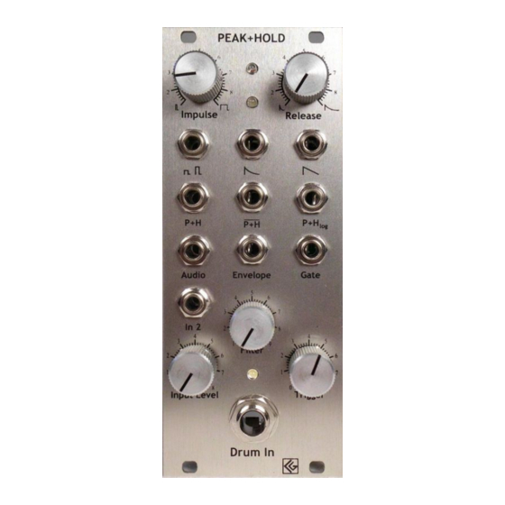
1. Description
The Peak & Hold allows one to play and control analog synthesizer equipment
using a drum with a pickup or any other percussive signal source. It generates 9
different CV/signal outputs from one input source.
The P+H provides a dynamic hold voltage (linear and logarithmic), a dynamic impulse signal e.g. for
triggering filters or delays; a dynamic release signal (linear and logarithmic), an envelope and a gate
signal output. Additionally, the original sound signal is available for further signal processing. The input
stage is equipped with adjustable level and trigger controls and a filter for flexible adaptation of
different percussive instruments - such as long or short sounding, high or low drums and cymbals.
Furthermore, there is a 2
2. Features
– 9 different CV/signal outputs
– Manual level, trigger and filter controls of the input signal
– Selectable frequency band (for cascading 2 or more P+Hs)
– Pickup included
– Optional with banana or 3,5mm minijacks
Banana jack version
input to cascade two Peak+Holds or to add another signal source.
nd
Minijack version
– Eurorack module
– Width: 10 HP
– Dimensions:
128,5 mm x 50,5 mm
– Depth:35 mm
– Supply voltage: ±12V
– Consumption: max. 65 mA
PEAK+HOLD
5
5
4
6
4
6
3
3
7
7
2
8
2
8
Impulse
Release
P+H
P+H
P+H
log
Audio
Envelope
Gate
5
4
6
3
7
In 2
2
8
4
4
3
5
3
5
1
9
Filter
2
2
6
6
1
7
1
7
0
8
0
8
Input Level
Trigger
Drum In
Drawing
Pickup with 2m cable
1
Advertisement

Summary of Contents for CG Products Peak & Hold
- Page 1 Modular Peak & Hold Dynamic Percussion Interface 1. Description The Peak & Hold allows one to play and control analog synthesizer equipment using a drum with a pickup or any other percussive signal source. It generates 9 different CV/signal outputs from one input source. The P+H provides a dynamic hold voltage (linear and logarithmic), a dynamic impulse signal e.g.
- Page 2 18 19 15 16 13 14 Objekt in Pfade: Objekt in Pfade: Modular 3. Functions Drum In (1/4' jack socket) Input for a percussion instrument PEAK+HOLD Objekt in Pfade: pickup (or rhythm machine output etc.). Its level is adjustable with the "Input Level"-knob .
- Page 3 18 19 15 16 13 14 Modular Ground This socket only exists in the banana version of the Peak+Hold . The ground connection is required if the module is connected to external equipment, e.g. a rhythm machine. Within the 18 19 15 16 13 14 eurorack modular system the module is grounded by its power supply and the casing.
- Page 4 Falsche Zahlen Modular Impulse Time Regulates the length of the dynamic impulses at output "Impulse" . It also influences the shapes of the "Release" - and "Release log" -outputs. Falsche Zahlen Release Time Adjusts the length of the release shape of the Release" - and "Release log"...
-
Page 5: Frequency-Selective Mode
Modular 4. Settings Pickup There is a pickup and double-sided adhesive tape included to the Peak+Hold module package by standard, so it is easy to connect the P+H to any percussive instrument. The pickup is equipped with 1/4' jack and 2m cable. Suggestions: on tabletop bongo drum... - Page 6 18 19 15 16 Modular Objekt in Pfade: Objekt in Pfade: Falsche Zahlen Full frequency range High cut Low cut Typical settings of the filter trimmers Falsche Zahlen Example: Two Peak+Holds are patched together. The pickup amplitude for both P+Hs is controlled by the knob 'Input Level' of the 1 P+H.
- Page 7 Modular Objekt in Pfade: 5. Adjustments Backside PCB view: Preamp Gain 18 19 15 16 This Trimmer sets the preamplification for input "Drum In" 15 16 Hipass Filter Together with trimmer (lowpass filter) a simple filtering option is created. This special feature allows control over the P+H by selecting the inputs frequency band.
-
Page 8: Contact & Support
Modular The following is for completeness, however these settings should not be adjusted: Schmitt-trigger Hysteresis of the internal schmitt-trigger comparator. If you have accidentally shifted the settings, readjust the trimmer to mid position (12 o'clock). Monoflop1 Length of the minimal delay time required for amplitude detection before the Impulse Out signal is set.