Table of Contents
Advertisement
Quick Links
___________________________________________________________________________________________________________
Measuring, control and dosing
technology
for private pools
iQntrol
DOS MODBUS
As 01/2022 serial no. 84050
Measuring, control and dosing technology for pH correction and disinfectants
Subject to technical modifications
-----------------------------------------------------------------------------------------------------------------------------------------------------------------------------------------------------------------------------------------------------------------------------------------------------------------
Handelsstraße 8
Tel. +43 (0) 7435 58 488-0
www.peraqua.com
A – 4223 St. Valentin
info@peraqua.com
Advertisement
Table of Contents

Summary of Contents for Peraqua iQntrol DOS MODBUS
- Page 1 DOS MODBUS As 01/2022 serial no. 84050 Measuring, control and dosing technology for pH correction and disinfectants Subject to technical modifications ----------------------------------------------------------------------------------------------------------------------------------------------------------------------------------------------------------------------------------------------------------------------------------------------------------------- Handelsstraße 8 Tel. +43 (0) 7435 58 488-0 www.peraqua.com A – 4223 St. Valentin info@peraqua.com...
-
Page 2: Table Of Contents
iQntrol DOS-MODBUS Table of contents About this manual ..................................4 Scope of applicability ................................4 Target group ..................................... 4 Storage of the manual ................................4 Further information ................................. 4 Symbols used ................................... 4 Safety ......................................5 Intended use .................................... 5 Safety notices ................................... - Page 3 10.6 Redox electrode ................................. 34 Decommissioning - Overwintering - Storage ..........................34 Technical data ....................................34 Change history - IQntrol DOS MODBUS ............................35 Commissioning protocol ................................36 Spare part list....................................38 Personal notes ..................................... 39 Original manual in German Version 1.0.2 2022.10.06...
-
Page 4: About This Manual
iQntrol DOS-MODBUS About this manual 1.1 Scope of applicability This manual describes the installation, commissioning and operation of the device. The manual covers the POOLKLAR Touch XL starting with version -> see footer and cover sheet. 1.2 Target group Only persons who have received proper instructions regarding the device functions may operate the device. Electrical and water- side connection work may only be conducted by appropriately trained specialists. -
Page 5: Safety
DOS-MODBUS Safety 2.1 Intended use The IQntrol DOS MODBUS device is designed for carrying out measuring and control tasks when treating swimming pool water in private swimming pools. 2.2 Safety notices The operation manual must be consulted prior to installation, commissioning and maintenance work. Following the commissioning, the manual must be made available to the operator. -
Page 6: Important Facts About Swimming Pool Water Properties
iQntrol DOS-MODBUS Important facts about swimming pool water properties 3.1 Auxiliary hygiene parameters The following information is meant to offer a preliminary overview about the most important auxiliary hygiene parameters in the treatment of swimming pool water. Further information is available from your swimming pool dealer, the chemicals supplier, or the book trade. -
Page 7: Scope Of Delivery - Device Description
14. Suction set (not visible in image) The IQntrol DOS MODBUS is delivered as a ready-assembled unit. All parts are mounted on a plastic plate. This ensures a quick installation of the device. It also goes toward preventing potential execution errors on the part of the installation personnel, as far as possible. -
Page 8: Installation
iQntrol DOS-MODBUS Installation 5.1 Select installation location A freely accessible installation location should be selected to facilitate operation and subsequent maintenance tasks. The installation location must be protected from frost and the device may not be exposed to direct sunlight. 5.2 Mounting the device on the wall Select the installation height so that the device is located at eye level. -
Page 9: Installation Suggestion
5.6 Installation suggestion The following sketch shows an example of the integration of the IQntrol DOS MODBUS in the swimming pool’s water treatment cycle. In most cases, a measuring water withdrawal between the filter pump and the filter boiler is sufficient. The water is recirculated into the clean water line downstream of the heat exchanger. -
Page 10: Commissioning - Notices
iQntrol DOS-MODBUS Commissioning - Notices Before the device can be commissioned, the following measures must be implemented. You can find the position of the parts listed in the following under Item 4.4 Device description. 6.1 Control parameters The device is loaded with factory-defined control parameters; see Commissioning protocol on page 25/29. Please adjust the control parameters for your basin according to the required dosing performance and the desired set points. -
Page 11: Disinfectants
iQntrol DOS-MODBUS 6.7 Disinfectants Notice Please find out which chemical was used to disinfect the basin water prior to the commissioning. If a different disinfectant is used from now on, the following must be observed. If other disinfectants (e.g., organic chlorine (dichlorine) or “chlorine-free” disinfection chemicals) were used previously, a reduced redox voltage is displayed during commissioning. -
Page 12: Electrical Connection
iQntrol DOS-MODBUS Electrical connection 7.1 Open and close the casing Picture of slotted screw head Depending on the type of device, the display lid can be swivelled to the left or right for installation and maintenance work. The locking axle must be removed for swivelling. The locking axle is identified by the plastic slotted screws on both sides. -
Page 13: Overview Of The Connection Diagram
iQntrol DOS-MODBUS 7.3 Overview of the connection diagram DANGER! Risk of death due to high voltage. All electrical work on the device may only be conducted by properly trained specialists under compliance with the applicable safety regulations! 7.3.1 The power pack NT_SCHW-8 Fuse Current Function... - Page 14 Fuse Current Fuse type Function Micro fuse 315 mA 24 VDC sensors (without function in the IQntrol DOS MODBUS) Micro fuse Primary fuse power pack Micro fuse without function in the IQntrol DOS MODBUS Micro fuse 230 VDC outlet relay K2 and K3...
-
Page 15: The I/O Board Io_Schw-8
iQntrol DOS-MODBUS 7.3.2 The I/O board IO_SCHW-8 Fuses on the I/O board Fuse Current Fuse type Function Micro fuse 315 mA Outlet disinfection 24 VDC 315 mA Micro fuse Outlet pH regulation 24 VDC Original manual in German Version 1.0.2 2022.10.06 15/39... -
Page 16: The Measuring Amplifier Mv_Cprt_V1
Central control technology off (external OFF) The input Central control technology off (external OFF) is used for the controlled deactivation of the IQntrol DOS MODBUS via the swimming pool filter system’s central control. As long as the contact is open, there is no dosing, no heating of the basin water, no alarm message given. -
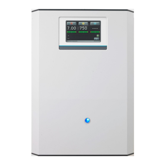
Page 17: Operating The Touch Screen
Colour red = pH regulation, yellow = disinfection The IQntrol DOS MODBUS has been deactivated by an external command from the swimming pool water treatment (filter system). There is no dosing, no heating of the basin water, no alarm message given. -
Page 18: Operating Programmes
iQntrol DOS-MODBUS 8.1 Operating programmes Depending on the operation state, the display shows different views. The following describes the main display views. 8.1.1 Automatic (auto mode) The device is in the status Automatic mode. The auxiliary hygiene parameters and the temperature (optional) are regulated based on set parameters. There is no disruption. -
Page 19: Alarm
iQntrol DOS-MODBUS 8.1.5 Alarm An alarm occurs; this is signalled by the symbol in the OUT list. The alarm relay is activated. A differentiation is made between alarms (software alarms, e.g., alarm high, alarm low) and disruptions (switch inputs). In the event of alarms, the respective measuring value is illustrated in red. In the event of disruptions, the corresponding symbol appears in the IN list. -
Page 20: Main Menu Settings Ph
8.2.1.2 Main menu Settings Proportional disinfection, 2-point (chlorine, bromine) The IQntrol DOS MODBUS control is suitable for the dosing of different disinfectants. The disinfection outlet must be adjusted to the disinfectant used. According to the selected variant, the menu for setting the associated parameters changes. -
Page 21: Main Menu Settings Disinfection O2 (Active Oxygen)
iQntrol DOS-MODBUS 8.2.1.3 Main menu Settings Disinfection O2 (active oxygen) If active oxygen is used as a disinfectant, the disinfection outlet is set to time control. This deactivates the measuring of the redox voltage, and the operating menu is changed accordingly. ml ... - Page 22 iQntrol DOS-MODBUS Dosing impediments There are situations where no disinfection dosing is possible or where the dosing cannot be properly completed. This may be the case in the event of an empty disinfection container, a disruption in the measuring cell flow or a voltage failure, e.g. The controller stores the already dosed amount and attempts to add the remaining amount at the next possible point in time on the same day.
-
Page 23: Main Menu Settings Dosing Performance
Disinfection approx. 1.2 l/h Disinfection approx. 0.6l/h The IQntrol DOS MODBUS device series is delivered with a maximum dosing performance. Please determine the maximum available dosing performance by means of the commonly used calculation methods in accordance with the applicable national standards. -
Page 24: Main Menu Settings Temperature
iQntrol DOS-MODBUS 8.2.1.5 Main menu Settings Temperature Alarm low lower alarm value Set point the device attempts to reach this value Control range if the temperature falls below the set point minus the control range (hysteresis), the Temperature output will be activated Example: Set point 25 °C –... -
Page 25: Main Menu Settings System Password End User - Password Level 1
iQntrol DOS-MODBUS 8.2.1.8 Main menu Settings System Password End user – Password level 1 There is no factory setting for an end user password. Without an end user password, the controller assumes password level 1, i.e., normal parameter changes are possible. The four-digit password can be individually chosen and must be a number between 0000 and 9999. -
Page 26: Main Menu Service
iQntrol DOS-MODBUS Main menu Service 8.2.2 Input test a test programme for switch inputs Output test a test programme for pumps and relay outputs Info for the query of firmware versions Manual dosing O For carrying out a manual disinfectant dosing The desired disinfectant volume must be set For commissioning or if additional disinfectant is required The default value is 3,000 ml... -
Page 27: Main Menu Login
iQntrol DOS-MODBUS Main menu Login 8.2.3 The controller can be protected by a password against unauthorised access. For rules for password assignment, see 8.2.1.8 If a password has been assigned, this password must be entered under Login for future parameter changes. There is no factory setting for a user password Main menu ... -
Page 28: Main Menu Log Event Log Justage
iQntrol DOS-MODBUS 8.2.4.2 Main menu Log Event Log Justage Event Log Justage The adjustments made are listed in the adjustment event log. The maximum memory depth is 50 entries. Incorrect adjustments are also logged. The memory depth is 50 entries 8.2.4.3 Main menu ... -
Page 29: Main Menu Calibration
iQntrol DOS-MODBUS Main menu Calibration 8.2.5 pH (2-point) for calibration of the pH electrode pH (phenol red) For adjusting the pH display value according to a phenol red measurement mV - Redox for calibration of the redox electrode Not available for the time control O disinfection process The calibrations are text-guided;... -
Page 30: Main Menu Calibration Redox Electrode
DOS-MODBUS 8.2.5.3 Main menu Calibration Redox electrode As a rule, the IQntrol DOS MODBUS device series is delivered with the ½“ redox electrode. Therefore, the menu on the left must be selected. In the event that the device works with the classic redox combination electrode, please select the menu on the right. -
Page 31: Network Connection - Visualisation
The IQntrol DOS MODBUS device series has an implemented web interface. Access occurs via an Ethernet (LAN) interface. If a IQntrol DOS MODBUS is integrated in an existing home network, authorised network devices will be able to access it. This only requires that a common web browser is installed on the terminal devices, such as a PC laptop, tablet or smartphone. -
Page 32: Establish Network Access At The Device
iQntrol DOS-MODBUS 9.2 Establish network access at the device Main menu Settings System Network 9.2.1 Based on the network topology, the corresponding numeric blocks for IP- address, gateway and subnetmask must be assigned under the Network menu item. -
Page 33: Maintenance And Cleaning
iQntrol DOS-MODBUS 10 Maintenance and cleaning All required maintenance and repair tasks may only be done by properly qualified personnel. Required spare parts are available from your specialist dealer. Please observe the safety notices when handling chemicals and wear appropriate protective clothing. The following maintenance tasks must be carried out. -
Page 34: Dosing Cartridges
iQntrol DOS-MODBUS 10.5 Dosing cartridges Expansion tab As part of the annual maintenance, the two dosing cartridges should be replaced. To do so, compress the two lateral expansion tabs and pull the head from the motor shaft toward the front. -
Page 35: Change History - Iqntrol Dos Modbus
DOS-MODBUS 13 Change history - IQntrol DOS MODBUS device series First device version V1 from 11/2021 Serial no. 84050 to … Notice When ordering spare parts, please have the device serial number on the rating plate ready. For support requests, we need the exact information on the firmware currently used in the controller and the serial... -
Page 36: Commissioning Protocol
iQntrol DOS-MODBUS 14 Commissioning protocol During a "reset", all parameters are reset to the factory setting. After a "reset", all parameters must therefore be checked and readjusted to the basin. We therefore recommend that you enter the optimised, basin-specific parameters in this list. In addition, the electrodes must be calibrated after a "reset”! Settings menu Ex works setting... - Page 37 iQntrol DOS-MODBUS Settings menu Ex works setting Setting range Step during commissioning Optimised during operation Dosing performance - pH 8 sec. = 100% 1 – 8 sec - Disinfection 15 sec. = 100 % 1 – 15 sec - Cycle time - locked 30 seconds 30 –...
-
Page 38: Spare Part List
Please note that as a rule, the spare parts list only contains replacement parts for the standard devices. Customer-specific or order-specific special articles are not taken into account. When ordering replacement parts for IQntrol DOS MODBUS devices, please note that not all of the articles are suitable for all device versions. -
Page 39: Personal Notes
DOS-MODBUS OPTIONS Item number 0024854 OPTIONAL for IQntrol DOS MODBUS V3 - 2 Sa dosing pumps instead of SR10 (Dosing performance 150 up to 2200 ml/h – hose kit 08./1.6/3.2 x 1.6) 0014140 Pump housing Sa grey/anthracite 0013039 Roller support for peristaltic pump Sa blue 0013482 Hose set Sa 0.8x1.6-Ph blue marking...
Need help?
Do you have a question about the iQntrol DOS MODBUS and is the answer not in the manual?
Questions and answers