Advertisement
Quick Links
Important Safety Information
Failure to follow these warnings and cautions could result in personal injury, damage to the vessel, or poor
product performance.
See the Important Safety and Product Information guide in the stereo box for product warnings and other
important information.
This device must be installed according to these instructions.
Disconnect the vessel's power supply before beginning to install this product.
To avoid possible personal injury, always wear safety goggles, ear protection, and a dust mask when drilling,
cutting, or sanding.
When drilling or cutting, always check what is on the opposite side of the surface to avoid damaging the vessel.
You must read all installation instructions before beginning the installation. If you experience difficulty during
the installation, contact Fusion
Tools Needed
• Pencil
• Drill
5
• 16 mm (
/
in.) drill bit
8
3
• 2.5 mm (
/
in.) drill bit
32
5
• 16 mm (
/
in.) socket or wrench
8
• Phillips screwdriver
• Marine sealant (optional)
November 2022
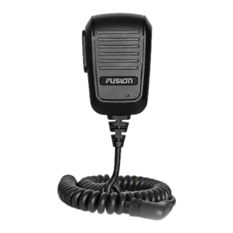
HANDHELD MICROPHONE
INSTALLATION INSTRUCTIONS
WARNING
CAUTION
NOTICE
®
Product Support.
GUID-1CD23792-2CC2-4768-B1BD-D1E11B6C23D8 v2
Advertisement

Subscribe to Our Youtube Channel
Related Manuals for Garmin FUSION

Summary of Contents for Garmin FUSION
- Page 1 When drilling or cutting, always check what is on the opposite side of the surface to avoid damaging the vessel. You must read all installation instructions before beginning the installation. If you experience difficulty during the installation, contact Fusion ®...
-
Page 2: Connection Diagram
Connection Diagram You can securely mount the microphone connector in an accessible location Microphone connector (Installing the Connector Mount, page 4). You must connect these to the AUX IN connector on the stereo wiring harness. RCA connectors If the stereo has more than one AUX IN connector, you must connect to the AUX1 connector. -
Page 3: Specifications
THD+N (Vo = 1 Vrms, 1 kHz) Less than 0.1% Vrms Gain +18 ± 0.5 dB Load impedance (min.) 10k Ohm Operating voltage From 10.5 to 32 Vdc Current (at 14.4 Vdc) 0.005 A Fuse (not included) 3 A Water rating IEC 60529 IPX7 For more information, go to garmin.com/waterrating. - Page 4 Installing the Connector Mount Before drilling a hole to mount the connector, you should verify that the microphone cable is long enough to reach the back of the stereo and the connector mounting location. You can use the included hardware to mount the connector on the end of the microphone cable onto the dashboard or other mounting surface.
- Page 5 9 Feed the connector through the back of the mounting surface. 10 Secure the connector and weather cap to the mounting plate using the nut NOTICE If you disconnect the microphone from the connector, you should secure the weather cap to avoid corrosion on the connector contacts.
- Page 6 Connection Diagram You can securely mount the microphone connector in an accessible location Microphone connector (Installing the Connector Mount, page 4). You must connect these to the AUX IN connector on the stereo wiring harness. RCA connectors If the stereo has more than one AUX IN connector, you must connect to the AUX1 connector.
- Page 7 > SETTINGS > SOURCE > AUX1. 4 Select PARTYBUS ENABLED to clear the checkbox. When you clear the checkbox, the AUX1 source is no longer available for streaming over the Fusion PartyBus network. It is recommended to disable network streaming for the microphone source to avoid ™...
- Page 8 , the Garmin logo, Fusion ® , and the Fusion logo, are trademarks of Garmin Ltd. or its subsidiaries, registered in the USA and other countries. These trademarks may not be used without the express permission of Garmin. M/N: A13014 For more information, go to garmin.com/waterrating.
Need help?
Do you have a question about the FUSION and is the answer not in the manual?
Questions and answers