Table of Contents
Advertisement
Quick Links
Advertisement
Table of Contents

Subscribe to Our Youtube Channel
Summary of Contents for Innova 3360
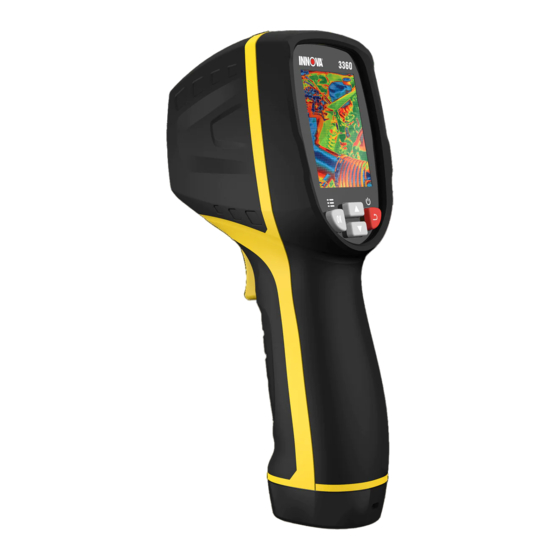
- Page 1 Thermal Imager OWNER’S MANUAL 3360...
-
Page 2: Table Of Contents
Table of Contents QUICK USE GUIDE GENERAL OPERATION STEPS ..........INSTRUMENT POWER SUPPLY ..........INFRARED THERMAL IMAGING DISPLAY INFORMATION ..ABSTRACT ....................... CHARACTERISTIC ................... TECHNICAL INDICATORS ................SKETCH MAP ....................POWER SUPPLY ....................BUTTON OPERATION ..................SETTINGS MENU EMISSIVITY ADJUSTMENT ............UNIT SETTINGS ................ -
Page 3: Quick Use Guide
Quick Use Guide GENERAL OPERATION STEPS GENERAL OPERATION STEPS 1. Long Press “Back/Power ” button for 3 seconds - Instrument will switched on, the screen will display the boot screen, and the thermal image will appear after the boot screen appeared. 2. -
Page 4: Infrared Thermal Imaging Display Information
Quick Use Guide Infrared Thermal Imaging Display Information Emissivity Time Battery Capacity Center Temperature Target Temperature Color Bar Minimum Temperature Position Maximum Temperature Position Maximum Temperature 10. Minimum Temperature... -
Page 5: Abstract
ABSTRACT ABSTRACT The device is a professional thermometer, the instrument adopts 32 x 32 pixels of thermal imaging sensors and a 30w pixels of photoelectric sensors, in addition with a 2.0” TFT LCD color display. Combined with infrared thermal imaging and temperature sensor and optical sensor images of auxiliary, able to provide a rapid, simple and accurate for most of the surface temperature of detection, the location of the specific and clear understanding of the object surface temperature. -
Page 6: Technical Indicators
TECHNICAL INDICATORS TEMPERATURE Temperature Range ......-20 to 600°C (-4 to 1112°F) Temperature Measurement Accuracy . ±2% ±2°C (±3.6°F) as tested at 25°C (77°F) Screen Shot Rate Correction ....IMAGE PERFORMANCE Image Capture Frequency ....Sensor Type .......... Non-refrigerating heat release point Thermal Sensitive(netd) ...... -
Page 7: Sketch Map
SKETCH MAP LCD Display Screen Up Button Confirm/Menu Button Back/Power Button Down Button Battery Cover Lanyard Hole Visible Light Infrared Sensor 10. Trigger Button (HOLD Key) 11. Micro USB Interface... -
Page 8: Power Supply
POWER SUPPLY Long press “Back/Power ” button 3 second to open or turn off the Thermal Image device. This device is powered by 3pcs “AAA” batteries, when the battery is full, the battery status icon in the upper right corner of the display shows full white full size “... -
Page 9: Button Operation
BUTTON OPERATION Except HOLD button, the Thermal Image device has four control buttons on the button of the display screen. Tip: Use the thumb button to control the trigger with the index finger 1. Back/Power Button “ ” Long press: Repeatedly open turn off the meter power. Short press: Exit menu option or drop storage photos. -
Page 10: Settings Menu
SETTINGS MENU In scan measurement mode, press the “Confirm/Menu OK” Button, to enter the settings menu overview, as shown below: The yellow highlight bar in the menu option corresponds to the selected option, press “Up ” and “Down ” Button scroll highlight bar Press “Confirm/Menu OK”... -
Page 11: Unit Settings
SETTINGS MENU Unit Settings Press the “Back/Power ” Button, to exit the emissivity setting interface, the emissivity value is not modified. UNIT SETTINGS Unit settings can be set to different unit displays. After entering the unit options, the interface is as shown below: Press the “Up ”... -
Page 12: Limit Value Setting
SETTINGS MENU Limit Value Setting LIMIT VALUE SETTING After entering the Limit Value option, the interface is as shown below: Press the “Up ” Button, the yellow highlight bar moves to another option. Press the “Down ” Button, and the yellow highlight bar moves to another option. -
Page 13: Date And Time
SETTINGS MENU Date and Time Press “Back/Power ” Button, to exit the color table setting inter face, the color table display will not be modified. DATE AND TIME After entering the date and time option, the interface is as shown below: The yellow highlight bar corresponds to that option, and correspondingly changes the value in that option. - Page 14 SETTINGS MENU Storage Highlight the selected picture, as shown below: The white box shows the picture stored in the internal memory of the meter. Press the “Up ” Button, the blue highlight bar will move up. Press the “Down ” Button, and the blue highlight bar moves down. Press the “Back/Power ”...
-
Page 15: Alarm
SETTINGS MENU Alarm Press the “Confirm/Menu OK” Button, select “Yes” to confirm the deletion of the picture, and that the window is closed automatically and the next saved picture is displayed. Press the “Back/Power ” Button, and select “No” to cancel deleting the picture, Confirm that the window is automatically closed. - Page 16 SETTINGS MENU Alarm Press the “Up ” Button, the high temperature alarm threshold will increase; long press can increase continuously Press the “Down ” Button, the high temperature alarm threshold will decrease; long press can reduce continuously. Press the “Confirm/Menu OK” Button, to open or close the start button “...
-
Page 17: Backlight Adjustment
SETTINGS MENU Backlight Adjustment BACKLIGHT ADJUSTMENT After entering the backlight adjustment options, the interface is as shown below: Press the “Up ” Button, to increase the brightness of the display backlight; long press can increase continuously. Press the “Down ” Button, the display backlight brightness will decrease;... -
Page 18: Language Selection
SETTINGS MENU Language Selection Press the “Up ” Button, and the yellow highlight bar moves up. Press the “Down ” Button, and the yellow highlight bar moves down. Press the “Confirm/Menu OK” Button, to confirm changing the fusion distance corresponding to the current color bar and exit the Fusion distance setting interface. -
Page 19: Information
SETTINGS MENU Information INFORMATION This option shows the factory information, version number, etc. of the instrument. Enter the information options, the interface is as shown below: Model Model of Instrument Serial Number of Instrument Version Version Number Release Date Factory Date Press the “Back/Power ”... -
Page 20: System Upgrade And After Sales Support
SYSTEM UPGRADE AND AFTER SALES SUPPORT SYSTEM UPGRADE AND AFTER SALES SUPPORT Concerned about the company’s dynamic information, the first time you can understand the latest upgrade information about firmware. If there is firmware’s update information, contact your local after-sales dealer to upgrade the firmware. -
Page 21: Emissivity Table
ADDENDUM Emissivity Table SUBSTANCE EMISSIVITY Pitch ............0.90 to 0.98 Concrete ..........0.94 Cement ..........0.96 Sand ............0.90 Soil ............0.92 to 0.96 Water ............0.92 to 0.96 Ice ............0.96 to 0.98 Snow ............0.83 Glass ............0.90 to 0.95 Ceramics .......... -
Page 22: Battery Installation
BATTERY INSTALLATION BATTERY INSTALLATION Battery pack must be installed in correct orientation. Look for arrow on battery pack for direction of insertion. - Page 23 NOTES...
- Page 24 MRP 93-1138 REV A Copyright 2021 IEC. All Rights Reserved. Copyright 2021 IEC. All Rights Reserved. Copyright 2021 IEC. All Rights Reserved.
Need help?
Do you have a question about the 3360 and is the answer not in the manual?
Questions and answers