Advertisement
KNX
Installation and operating instructions B.E.G. KNX Room Controller
1. General information
The B.E.G. KNX Room Controller, abbreviated RCT, is a control unit
for B.E.G. KNX occupancy detectors as well as other loads. The occu-
pancy detector and the other loads are connected to the B.E.G. RCT
by means of a plug connector system. The B.E.G. RCT controls several
functions of a room based on the KNX bus.
The integrated DALI/KNX gateway offers the possibility to use DALI
electronic ballasts, which are becoming more and more popular.
The DALI lights of a room are dimmed or switched depending on
presence. Furthermore, an integrated actuator offers the possibility to
actuate the blinds. Additionally, in the "service" mode, it is possible to
control the lights or the blinds manually by means of two push button
inputs. This offers the possibility to turn the lights on or off and to ac-
tuate the connected loads even without ETS. Therefore, the lights and
the blinds can be used immediately during installation. After having
finished the installation, the push button inputs can be programmed as
desired for KNX operation.
2. Application programs
Currently, the following application programme is available:
RCT V1.0
Instructions see application description (to be downloaded on the
B.E.G. homepage)
3. Safety instructions
Risk of death by electric shock
!
The device must only be installed and commissioned by an
!
accredited electrical engineer.
Please follow country-specific safety and accident prevention
!
rules as well as all current guidelines.
!
The device is intended for interior installation in dry rooms.
For installation, the device has to be switched to zero potential.
!
Do not open the device! Defective devices have to be returned
!
to the manufacturer.
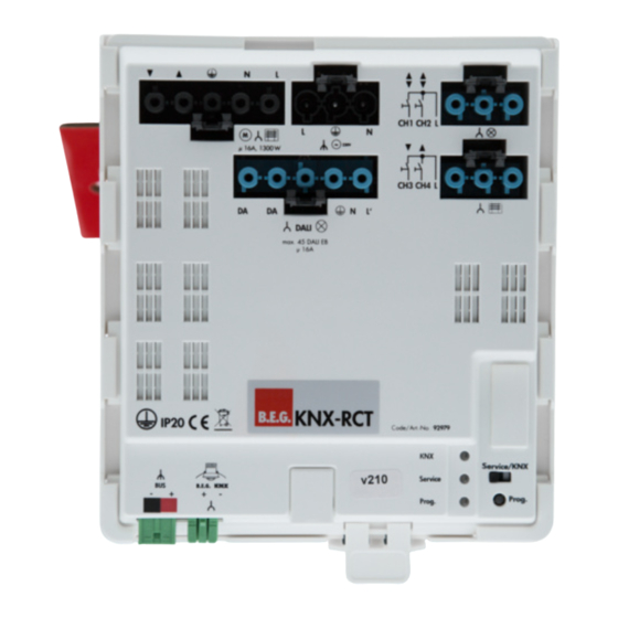
4. Connections
a)
b)
N
L
L
N
3600W, cosϕ = 1,
M
1800 VA, cosϕ = 0,5
~
230V
N
DA
DA
L'
DALI
max. 45 DALI EB
d)
IP20
BUS
B.E.G.
-
+
-
+
f)
a) Shutter/Blind
e) Pushbutton Shutter/Blind
b) Power supply
f) BUS
c) Pushbutton light
g) Service/KNX
d) DALI ECG/L'
h) Programming button
Room Controller RCT
5. Mounting and installation of the B.E.G.
KNX Room Controller
1.
B.E.G.'s KNX Room Controller consists of a base plate and the pow-
er element. In order to loosen the snap-fit between base plate and
power element, press the respective clip situated between the service
switch and the middle of the RCT on the bottom end.
Pull the power element in the slide rail in order to separate the two
parts from each other. The base plate is equipped with openings.
Please drill holes at the desired mounting place which correspond to
these openings and mount the RCT by means of screws. Afterwards,
please insert the power element in the slide rail of the base plate and
lock it into place.
a)
Base plate
b)
Power element
c) Openings for screws
d) Clip
2.
B.E.G.'s KNX Room Controller is connected to mains by means of the
respective connection cable.
This work has to be done by an authorised electrician only.
!
Before starting, always disconnect the fuse in the incoming
circuit from the supply.
L
N
c)
KNX-BUS
1
2
L
3
4
L
e)
Code/Art.-No.: 92979
KNX
Power cord:
Blinds:
DALI:
g)
h)
KNX:
Pushbutton:
!
PIR occupancy detector obligatory!
a)
c)
b)
KNX-RCT 92979
DALI-EVG
(Connection diagram)
Wieland Nr. 92.931.3053.1 black
Wieland Nr. 92.954.4053.1 black
Wieland Nr. 92.954.4453.0 blue
Wieland Nr. 93.421.0553.1 green and
Wieland Nr. 93.422.0553.1 green
Adels
Nr. 162463P
blue
3.
The B.E.G. KNX Room Controller is connected to the KNX bus by
means of the respective connection cable (green plug connector "Bus"
at the left bottom side).
!
Please respect the correct polarity (+/-).
4.
The other loads are connected to the B.E.G. KNX RCT using the
respective connection cables. An easy installation is ensured by the
different colours of the cables and the shape of the plug connector.
6. Putting into operation and programming
The "Service/KNX" switch is for operating the B.E.G. KNX Room
Controller even without using ETS. The switch being in its "Service"
position (left side), the basic functionality of the connected loads is
given without ETS. After installation in ETS or if the service mode is
no longer required the switch is put into its "KNX" position and all
connected loads are controlled as programmed in ETS.
The current mode is indicated by LEDs:
a) green
LED: KNX-Betrieb
b) yellow LED: service mode
c) red LED:
The RCT is in its programming mode (pressing the pro-
gramming button beneath the "KNX/Service" switch starts
thex programming mode).
KNX
All B.E.G. KNX occupancy detectors cooperate
with the RCT.
EN
BUS
B.E.G.
-
+
+
-
KNX
Advertisement
Table of Contents

Related Manuals for B.E.G. KNX Room Controller

Summary of Contents for B.E.G. KNX Room Controller
- Page 1 5. Mounting and installation of the B.E.G. KNX Room Controller The B.E.G. KNX Room Controller is connected to the KNX bus by The B.E.G. KNX Room Controller, abbreviated RCT, is a control unit means of the respective connection cable (green plug connector “Bus”...
- Page 2 9. Article / Part no. / Accessory Maximum start-up current (150µs/600µs): 700A / 370A (time indication for pulse Part.-No. width for 10% of the peak current, UL definition KNX Room Controller 92979 Maximum load: Incandescent lamp: Connector Set RCT 92983 Fluorescent lamps T5/T8:...
Need help?
Do you have a question about the KNX Room Controller and is the answer not in the manual?
Questions and answers