Advertisement
Quick Links
Advertisement

Subscribe to Our Youtube Channel
Related Manuals for Kydera CDR-300UV

Summary of Contents for Kydera CDR-300UV
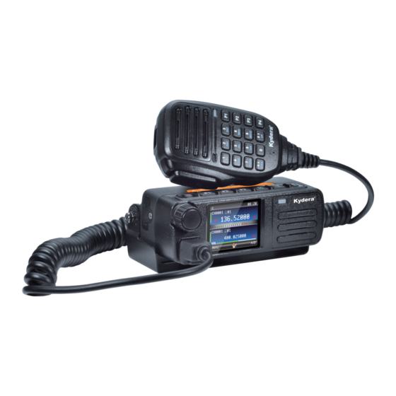
- Page 1 PORTABLE FM TRANSIVER CDR-300UV SERVICE MANUAL/维修手册...
-
Page 2: Ordering Replacement Parts
GENERAL/概述 INTRODUCTION 引言 SCOPE OF THIS MANUAL 本手册的范围 本手册是提供给熟悉通信专业并且具有维修经验的技术人员 This manual is intended for use by experienced technicians 使用的。 它包括了维修该设备所 需要的全部资料和现行公布 familiar with similar types of commercial grade communications 的数据。在出版 后可能发生变动,如果需要,可以使用《维修 equipment. It contains all required service information for the 通报》或《手册修订本》进行补充。... - Page 3 模式 MODES 用户模式 PC模式 USER MODE PC MODE 类型 MODES 模式 功能 FUNCTION 用户模式 用于普通操作 User mode For normal use. Used for communication between the radio Used for communication between the radio 计算机模式 PC mode and a PC and a PC How to enter each mode PROCEDURE MODES...
-
Page 4: Circuit Description
电路说明 CIRCUIT DESCRIPTION 接收部分 1. RECEIVER 前级(射频放大器) Front Amplifier(RF AMP) 从天线输入的接收信号经低通,经过二极 The signal coming from the antenna 管收发转换电路,在射频放大器 Q3,Q4 被 input via the low-pass, through the diode 放大, 其中 V 段线圈 L28,L30,L32,L16,L20 transceiver conversion circuit, 构成选频带通; U 段线圈 L15,L17,L21 构成 amplified by the RF amplifiers Q3 and 选频带通,通过开关... -
Page 5: Ctcss Dcs
发射部分 2. Transmitter 发射音频 Transmitter audio 信号有话筒产生 The signal is generated by microphone 模拟信道: 送入到 FD6818 进行调频等处理 Analog channel: sent to FD6818 for 后输出。 frequency modulation other 数字信道:送入基带处理器 C7000 进行采 processing, then sent out 样、编码、压缩、I/Q 调制输出到 FD6818 Digital channel: sent into the baseband 进行调频等处理后输出... - Page 6 天线转换开关和 LPF ANT switch and LPF U 段时:末级功率放大器输出的信号经 U: The signal output by final power amplifier 过 D5 和由 L14.L22,L25,L23,L17 组成 passes through diodes D5 and is composed of 带通滤波器后从天线端子发射出去。 L14, L22, L25, L23 and L17 to form a band D5,D10 一起构成了收发转换开关。...
-
Page 7: Control System
5. 控制系统 5. Control system U1 微处理器以 24MHZ 工作 U1 microprocessor works at 24MHZ. 音频放大器 6. Audio amplifier 模拟信号由 FD6818 9 脚输出,数字信 The analog signal is output thru pin 9 of 号由 C7000 输出, 再由音频功率放大器 FD6818, and the digital signal is output by U4,(SA58632)放大后驱动扬声器。... - Page 8 芯片的引脚功能 FD6818 电源 AVDD Power supply 时钟线 SCLK Clock input for serial control bus 数据线 SDIO Data input/output for serial control bus 电源 AVDD Power supply 晶体引脚 XTAL1 Oscillator pin1 晶体引脚 XTAL2 Oscillator pin2 控制接口的选择 MODE Control interface select 置位 SENB Latch enable(active low) input for serial control bus 音频输出...
-
Page 9: Parts List/零件表
PARTS LIST/零件表 CAPAVITORS CC 45 TH 1H 220 J .Caoacitor value 4 5 6 CC45 Colir 010=1pF 2 2 0=22pF 1=Type…ceramic,electrolyitc,etc. 4=Voltage rating 100=10pF 2=Shap…round,square,ect. 5=Value 101=100pF Multiplier 3=Tenp.coefficient 6=Tolerance 102=1000pf=0.001uF 2nd number 103=0.01uF 1st number .Tenperature coeffictrolytict 1st Word 2nd Word Color Black... - Page 10 型号:CDR-300UV MCU 电子部份 序号 器件编号 规格描述 位置 备注 应发 材料名称 Type Nam 用量 Parts No. Description Standard Remark 数量 主板 100-DR200MFD-300 C7DR300UV-MCU-FD-51M-2.0 2020.08.21 R474 R473 R92 R90 R89 R7 R26 R158 R138 R137 R131 R126 R125 R119 R118 R117 Resistor...
- Page 11 型号:CDR-300UV MCU 电子部份 序号 器件编号 规格描述 位置 备注 应发 材料名称 Type Nam 用量 Parts No. Description Standard Remark 数量 主板 100-DR200MFD-300 C7DR300UV-MCU-FD-51M-2.0 2020.08.21 R474 R473 R92 R90 R89 R7 R26 R158 R138 R137 R131 R126 R125 R119 R118 R117 Resistor...
- Page 12 C240 C239 C77 C31 C22 C19 C177 C158 C148 C143 C138 C123 C12 C117 C112 C100 C99 C94 C92 C29 C28 29 Capacitor 105-1104104P-K10 104P/16V 0402 ±10% C27 C26 C25 C20 C13 C120 C116 C103 C102 C207 C213 C7 C197 C193 C180 C122 C238 C156 C46 C45 C36 C170...
- Page 13 SOT23- 64 SMT IC 101-104B332M-120 XC6204B332MR U37 U36 U35 U13 SOT23- U34 U33 U32 U31 U18 65 SMT IC 101-104B502M-120 XC6204B502MR SOT- 66 SMT IC 101-18121ABC-120 SY8121ABC 67 SMT IC 101-1AT2659X-000 AT2659 68 GPS module 101-15N71XXX-000 5N71 SOT- 69 SMT IC 101-1HRV3000-120 ALPU-MP 70 SMT IC...
- Page 14 规格描述 位置 备注 应发 序号 器件编号 材料名称 Type Nam 用量 Parts No. Description Standard Remark 数量 C7DR300UV-TX-51M-FD-4.0 四层 TX双功率 100-DR200TXX-400 2021.04.12 板 Resistor 104-11040RXX-J00 0402 ±5﹪ R36 R35 R25 R57 Resistor 104-110410RX-J00 0402 ±5﹪ Resistor 104-110422RX-J00 0402 ±5﹪ C131 Resistor 104-110447RX-J00 0402 ±5﹪...
- Page 15 49 Capacitor 105-1108100P-J10 100P/50V 0805 ±10% 50 Capacitor 105-11081P5X-CF0 1.5P/250V 0805 ±0.1% 250V C97 C105 C60 51 Capacitor 105-11082PXX-CF0 2P/250V 0805 ±0.1% 250V C114 52 Capacitor 105-11083PXX-CF0 3P/250V 0805 ±5% 250V C100 C7 C50 53 Capacitor 105-11084PXX-CF0 4P/250V 0805 ±5% 250V 54 Capacitor 105-11085PXX-CF0...
- Page 16 接收板 电子部份 序号 器件编号 规格描述 位置 备注 应发 材料名称 Type Nam 用量 Parts No. Description Standard Remark 数量 C7DR300UV-RX-51M-FD-4.0 四层 RX板 100-DR200RXX-400 2021.04.12 板 R9 R3 R11 C70 C141 C123 R22 R13 C235 R34 R14 R12 R10 R1 C90 C142 C134 C124 Resistor 104-11040RXX-J00 0402...
- Page 17 C218 C7 C372 C373 42 Capacitor 105-1104100P-J10 100P/50V 0402 ±0.25% C374 C382 C176 C201 C204 C209 43 Capacitor 105-1104120P-J10 120P/50V 0402 ±10% C241 C236 C121 C79 C80 C155 44 Capacitor 105-1104470P-J10 470P/50V 0402 ±10% C158 C232 C231 C227 C226 C228 C233 C246 C181 C170 C95 C97 C283 C8 C49 C4 C65 C87 C81 C98 C88 C82...
- Page 18 85 Crystal 110-126MXX00-060 26MHz DA SO3225 86 Crystal 110-132K7603-000 32.768K S3215 FC-135 87 Crystal 110-351M5500-100 51.550M ±5 配对 XF2 XF1 20PIN 88 20-pin horizontal s 122-12005020-000 下接 (RF_DOWN) J505 89 40-pin horizontal s 122-12005040-000 40PIN 下接 J912 90 Feedline 130-113050XX-030 不带端L=50MM,线径1.13MM 91 RF wire 130-113067XX-030...
- Page 19 ADJUSTMENT/调整 所需的测试设备 Required Test Equipment 1.稳定电源 1. Stabilized Power supply 1.输出电源在5V和9V之间可调,并且电流为3A或更大。 1. The supply voltage can be changed between 5V 2.标准电压为6.5V。 and 9V, and the current is 3A or more. 2. The standard voltage is 6.5V. 2.电流表 2. DC Ammeter 1.高级电流表(17档和其它功能)...
- Page 20 Squelch Level, S meter Level, Lo Power, QT Deviation, DQT Deviation, and battery warning. Section common to the transmitter and receiver VCO Measurement Adjustment Specifications Item Condition /Remarks Test equipment Terminal parts Method Setting Power supply voltage battery terminal: 6.5V lock CH: TX low Digital voltmeter...
- Page 21 静噪级别,S计电平,低功率,QT偏差,DQT偏差和电池警告 发射部和接收部共用部分(压控振荡器 ) 测量 调整 项目 条件 规格备注 测试设备 终端 部件 方法 设定 电源电压电池终端:7.4V CH: 发射低端频点 数字电压表 CH: 接收低端频点 压控振荡器 CH: 发射高端频点 少于 4.0V CH: 接收低端频点 接收部分 测量 调整 规格备注 项目 条件 终端 方法 测试设备 部件 带通滤波器 CH: 接收中心频点 调整频谱波形 Tra发生器...
-
Page 22: Adjustment Frequency List
ADJUSTMENT FREQUENCY LIST Description TX f(MHz) R X f(MHz) 155.500MHz Center 155.025MHz 136.025MHz 136.025MHz 173.975MHz 173.975MHz 调整频率清单 描述 信道 发射频率 (MHz) 接收频率 (MHz) 中心 155.025MHz 155.025MHz 底 136.025MHz 136.025MHz 高 173.975MHz 173.975MHz ADJUSTMENT FREQUENCY LIST Description TX f(MHz) R X f(MHz) Center 440.025MHz 440.025MHz... -
Page 23: Block Diagram
BLOCK DIAGRAM YZ3312 2SC4226 FD6818 3SK318 YZ3312 2SC4226 D19,D20 HVC131 D17,D18 HVC131 24MHz DSB321SCL WX4818 C7000 SGM721XN51TR SA58632BS DMR_AF NLAS4157DFT2G TC58CVG1S3HRAIGBAJ SPK_SHTD 13.8V B546 ALPU-MP GD25Q16CEIG... - Page 24 MCU 布 C7000 彩彩部部 13.8V EFUSE R114 DVSS PR_V MCU-3V3 100K DVSS SPI0_SCLK KEYPAD_P3 104P 104P 104P 104P R3 33R SPI0_SCLK PTB20 DVSS DVDD33 R115 SPI0_MOSI KEYPAD_P5 R113 SPI0_MOSI PTB22 R5 33R DVSS DVDD33 SPI0_MISO KEYPAD_P4 VOTAGE C121 SPI0_MISO PTB21 R1 33R DVSS DVDD33...
- Page 25 RDA_SQ C160 RF_3.3V TXU_5V0 104P T/R_SW 104P C165 R1011 R1012 1N4148WT 102P C159 C162 TXV_5V0 发发发发发发 ( 采话彩采采采采采采 ) RF_3.3V 300R C161 C151 270NH AVDD C152 300R C145 1N4148WT RDA_CK C155 47NH TX_VU_OUT RF_3.3V SCLK 470P C163 AVDD RDA_DA SDIO 102P 104P C158...
- Page 26 C784 3.5*4.7*0.8 102P 3.5*4.7*0.8 C884 102P 注注,音音发音音我音音芯音音音 音音音音音我音音 RF5V0 SP_JACK SP_VOL_SW JACK1 100R 220P SP_JACK SP JACK UART1_TXD T1RXD_PTT JACK2 C514 100R MIC JACK 104P RF_ANTV_EN UART1_TXD RF5V0 T1RXD_PTT UMC4N 100P RF_3.3V 8TV_SW TXU_5V0 TXV_5V0 SP_VOL_SW 39nH 470P 102P RF_ANTV_EN RF_ANTU_EN RF_APC 103P...
- Page 27 全全全发 D111 R201 LED-KEY 100R 100R 910R RED_LED DTC144EE LCD_K KEY_LIGHT 2SC4919 220R DR-300UV 产产产 TFT 彩彩彩发彩彩彩彩 GREEN 100R GREEN_LED DTC144EE 220R 910R LCD_K LED- R172 LED+ R147 LCD_RESET RESET R148 LCD_RD/A0/UART3_RXD LCD_DB0/SDA R149 C179 LCD_RS/SCK R145 104P R146 VDDA/2.8V R143 R173 VDDIC/1.8V...
- Page 28 发发发发发 3.3K RED_LED TX PTT 220P PTT/RXD UART_TXD 102P 话话话芯话 104P 103P 102P ARM_RST NRST KEYPAD_LIGHT SWDIO OSCIN/PA1 PD1(HS)/SWIM KEYPAD_P1 SPI_MISO OSCOUT/PA2 PC7(HS)/SPI_MISO[TIM1_CH2] SPI_MOSI SWDIO PC6(HS)/SPI_MOSI[TIM1_CH1] SPI_SCK VCAP PC5(HS)/SPI_SCK[TIM2_CH1] ARM_RST KEYPAD_P2 PC4(HS)/TIM1_CH4/CLK_COO/AIN2/[TIM1_CH2N] JTAG 测测测 , 布布布布布布布布 104P KEYDA_IN PTT/RXD STM8S003F3 102P 22UF(0805) 104P...
Need help?
Do you have a question about the CDR-300UV and is the answer not in the manual?
Questions and answers