Table of Contents
Advertisement
Quick Links
Advertisement
Table of Contents

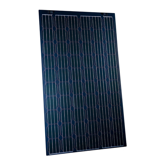
Summary of Contents for Sunflare FLEX60
- Page 1 Installation Instructions for the FLEX60 Photovoltaic Modules...
- Page 2 Installation Instructions for the FLEX60 Photovoltaic Modules Introduction FLEX60 modules are not intended for installation by unqualified end users. These instructions are This manual provides important safety to be retained for future reference in case of instructions for the Sunflare FLEX60 module and maintenance, ownership change, or disposal.
- Page 3 The requirements of the National Electrical • Danger! The FLEX60 modules may become Code (NEC) in Article 690 shall be followed slippery when wet. This could cause a slip to address these increased outputs. In hazard.
-
Page 4: Installation Safety
• Danger! Never open electrical connections • Only Butyl based adhesives are certified (such as connectors) when the circuit is under to adhere the Flex60 modules to a roof load. membrane. • Danger! Contact with electrically charged •... -
Page 5: Handling Safety
Failure to protect the electrical responsible for proper support structure connections could result in electrical arcs design. Sunflare is not responsible for leading to fire and possibly shock hazards. supporting structures, including but not limited to the roof structure. -
Page 6: Mechanical Installation
Failure to properly clean the roofing membrane The FLEX60 module is certified by CSA as part can result in much lower load capacities than of a Class A roofing system per UL 790 when... - Page 7 Only HelioBond PVA 600BT by HB Fuller has been approved for use with Sunflare modules and wire trays. Do not use any other adhesive. Doing so could void your warranty and lead to product failures.
-
Page 8: Electrical Installation
Electrical Installation Modules in Series The FLEX60-160W to FLEX60-185W modules are strung in pairs to match power ratings for typical MLPE devices. Electrically connect adjacent modules (across rows) using 1’ jumper cables as shown in Figure 4. Jump only one j-box per module. - Page 9 “FLEX60 Installation Supplement” document. Grounding Per its certification, the Sunflare FLEX60 module is not to be grounded. It is double insulated and has no exposed metal components. Ensure you use only no conductive polymeric wire...
-
Page 10: Maintenance And Repair
Whenever possible use the jumper cables string with the damaged module from all other provided by Sunflare. They are cut to the correct strings and use black out blankets to cover all size and have the proper mating connectors for modules in that string. -
Page 11: Physical Dimensions
Sunflare_FLEX60_Installation_instruction_V7 11/12/2020 Sunflare_FLEX60_Installation_instruction_V8 04/19/2021 Liability Limitation Sunflare is not in control of the installation of the module and hence does not accept responsibility nor liability for damages arising from improper use, incorrect installation, operation, or maintenance of the product. The information provided by this manual is based upon Sunflare’s knowledge and understanding... - Page 12 “Z” suffix indicates the size of cells (127mm x 127mm), blank is default size (156mm x 156mm). Cell technology is CIGS with bypass diode for each cell. Cell Size Model Size Pmax Model (mm) (mm) (Vdc) (Vdc) FLEX60-XXXW 156 x 156 1660 x 990 38.00 7.70 30.30 6.60 37.60 7.60 29.86 6.53 36.93...
- Page 13 Cell Size Model Size Pmax Model (mm) (mm) (Vdc) (Vdc) FLEX30-XXXW 156 x 156 870 x 990 18.5 7.40 14.3 6.30 1070 x 828 1702 x 512 FLEX28-XXXW 156 x 156 1186 x 670 17.2 7.40 13.3 6.30 FLEX27-XXXW 156 x 156 1544 x 512 16.6 7.40...
- Page 14 (156mm x 156mm) Cell technology is CIGS with bypass diode for each cell. Cell Size Model Size Pmax Model (Vdc) (Vdc) (mm) (mm) FLEX60-XXXW-M20-A 156 x 156 1666 x 996 38.00 7.70 30.30 6.60 37.60 7.60 29.86 6.53...
- Page 15 ISC, VOC, and Pmax under standard test conditions (irradiance of 100 mW/ cm2, AM 1.5 spectrum, and a cell temperature of 25°C (77°F)). Liability Limitation Sunflare accepts no liability for damages of any kind, as a result of the use of the information contained in this instruction. Sunflare is not in...


Need help?
Do you have a question about the FLEX60 and is the answer not in the manual?
Questions and answers