Table of Contents
Advertisement
Quick Links
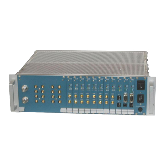
This user guide contains installation and technical information about three types of 2N
GSM Gateways :
2N StarGate , 2N BlueStar , 2N BlueTower.
In cases that feature will be same for all three types, gateway name will be "PRIGW". In the
other cases you find information for each type of gateway divided.
!! Preliminary version of user guide v1.8 !!
User Manual for
2
N
S
2
N
S
(
5
0
7
0
0
0
E
,
5
0
7
0
0
1
E
,
5
0
(
5
0
7
0
0
0
E
,
5
0
7
0
0
1
E
,
5
0
2
N
B
2
N
B
(
(
5
5
0
0
7
7
2
2
0
0
0
0
2
N
B
l
u
2
N
B
l
u
(
5
0
(
5
0
Version:
t
a
r
G
a
t
e
t
a
r
G
a
t
e
7
0
0
2
E
,
5
0
7
0
1
0
1
E
,
5
0
7
0
7
0
0
2
E
,
5
0
7
0
1
0
1
E
,
5
0
7
0
l
u
e
S
t
a
r
l
u
e
S
t
a
r
E
E
,
,
5
5
0
0
7
7
2
2
1
1
0
0
E
E
)
)
e
T
o
w
e
r
e
T
o
w
e
r
7
3
1
0
E
)
7
3
1
0
E
)
1.8p
1
0
E
)
1
0
E
)
Advertisement
Table of Contents

Related Manuals for 2N Telekomunikace 2N StarGate


Summary of Contents for 2N Telekomunikace 2N StarGate
- Page 1 This user guide contains installation and technical information about three types of 2N GSM Gateways : 2N StarGate , 2N BlueStar , 2N BlueTower. In cases that feature will be same for all three types, gateway name will be “PRIGW”. In the...
- Page 3 !! Preliminary version of user guide v1.8 !! Dear customer, We congratulate you on purchasing your 2N product. This new product was developed and produced with emphasis on maximum utility value, quality and reliability. Our wish is to make you satisfied with the StarGate / BlueStar / BlueTower (PRIGW) completely and for a long time.
-
Page 4: Table Of Contents
CONTENTS DESCRIPTION - GENERAL DESIGN ....................5 1.1............................5 IMENSIONS 1.1.1. Basic Dimensions........................5 1.1.2. Front Side Division........................5 1.1.3. Front side division for gateways with VoIP interface ............6 1.2........................6 VAILABLE OFTWARE 1.3..........................6 OWER UPPLY 1.3.1. Description ..........................6 DESCRIPTION – MAIN FEATURES ....................7 DESCRIPTION –... - Page 5 !! Preliminary version of user guide v1.8 !! 7.7.3. VoIP Board Configuration (Web Interface) ................36 8.7.3 VoIP Board Firmware Upgrade....................37 CONFIGURATION OF VOICE CALLBACK CENTER SOFTWARE........42 8.1.................42 CHEME OF FUNCTION OF OICE ALLBACK 8.2......................42 NSTALLATION AND LICENSES 8.3............47 ONFIGURATION OF OICE...
- Page 6 2N StarGate / BlueStar / BlueTower PRIGW is a compact yet highly sophisticated system. It supports full remote supervision and configuration via an IP network, or using an external modem over a BRI-ISDN and analog line, or over a B channel in a PRI-ISDN trunk. The system has been designed and works with a lot of highly sophisticated functions, which make it fully client-oriented and highly reliable in cooperation with both GSM networks and ISDN.
-
Page 7: Description - General Design
1.1.1.3 2N StarGate 3G Extension rack To use 2N StarGate with 3G extension card you need an extension rack (part No. 507050E). This 19“ subrack is 6U high and 360mm deep. Its front side open to accept plug-in boards. -
Page 8: Front Side Division For Gateways With Voip Interface
1.1.3. Front side division for gateways with VoIP interface The subrack width is divided into an 8HP-wide mains panel and 19 4HP-wide modules in the following sequence (from right to left): Board Type Size StarGate BlueStar BlueTower VoIP board 12HP CPU board AUX board PRI board... -
Page 9: Description - Main Features
!! Preliminary version of user guide v1.8 !! Description – Main Features Quick unit start – being free of an operating system (programmed in the processor code), the system is completely ready to work within 30 seconds following its power on/restarting. Of course, the full function time of all GSM modules depends on the actual load and capacity of GSM networks to which the PRIGW is connected. - Page 10 Example of call cost reduction with using of PRIGW with Thin VoIP card CZECH REP. PSTN SPAIN FRANCE network networks ISDN PSTN PSTN Company A ISDN network network Headquaters networks (Prague) ISDN BlueTower networks Internet proxy BlueTower BlueTower ISDN ISDN A (Paris) A (Madrid) BlueTower with Thin VoIP card you handle with 2xPRI ISDN interfaces, 4xVoIP-SIP...
- Page 11 !! Preliminary version of user guide v1.8 !! Detailed statistics – provides a detailed overview of the count of incoming and outgoing calls and their successful connections. The statistic data can be displayed either globally for the whole PRIGW, or for the selected GSM provider, or the selected GSM module (SIM card). These data are generated automatically.
- Page 12 Up to 64 SIM cards – each GSM board contains 16 SIM card holders. However, two SIM cards are only connected to the GSM modules at one moment. An intelligent SIM card switching according to time, at random intervals, according to completed minutes or sent SMS enables a client-oriented approach.
- Page 13 !! Preliminary version of user guide v1.8 !! No SW is necessary for configuration – system communicates through an RS232 interface and Telnet protocol using standard extended AT commands. However, high-quality software running under the Windows OS has been designed for user-friendly control and configuration. Fault diagnostics is very simple too –...
-
Page 14: Description - Plug-In Boards
Description – Plug-In Boards Warning: GSM boards are always locked for one type of gateway. See table below for more information: Plug-in board StarGate BlueStar BlueTower CPU card StarGate CPU card BlueStar CPU card BlueTower AUX card StarGate AUX card BlueStar AUX card BlueTower PRI card StarGate PRI card BlueStar... -
Page 15: Lithium Battery Replacement
!! Preliminary version of user guide v1.8 !! 3.1.3. Lithium Battery Replacement WARNING! Incorrect battery replacement may cause explosion. The battery can be replaced with a battery of the same or equivalent type only as recommended by the manufacturer. Handle used batteries as instructed by the manufacturer. -
Page 16: Configuration Jumpers
3.1.4. Configuration Jumpers There are three configuration jumpers on the CPU board. Jumper JP1 is intended for a change of the board addressing and is not used at present. It need not be applied during a common firmware upgrade. By default, jumper JP1 is disconnected. JP2 is intended for switching serial port between CPU board and optional extension board. -
Page 17: Aux Board
!! Preliminary version of user guide v1.8 !! 3.2. AUX Board 3.2.1. Board Description The AUX board contains a switching array and system of voice messages, controlled by an independent processor system separated from the system bus. The AUX port is used for making testing calls or recording voice messages. -
Page 18: Configuration Jumpers
3.2.3. Configuration Jumpers Default Default. Please don’t change JP4a 2,3 earphone, 1 +MIC, 4 -MIC JP4b 2,3 earphone, 4 +MIC, 1 -MIC JP4c 1,4 earphone, 2 +MIC, 3 -MIC JP4d 1,4 earphone, 3 +MIC, 2 -MIC JP3b - DISA Voice upload procedure Connector for analog headset JP3a - Operational status... -
Page 19: Pri Board
!! Preliminary version of user guide v1.8 !! 3.3. PRI Board 3.3.1. Board Description The PRI board contains an one or two ISDN interfaces and PCM bus timing circuits. PRI 1 interface is designed as internal (on this port is activated LCR function), PRI 2 port is designed as external (all calls from the port will be routed to PRI 1 port). -
Page 20: Configuration Jumpers
3.3.2. Configuration Jumpers PRI 2 PRI 1 Default. Please don’t change Default. Please don’t change Active Disable RJ45 connector for PRI-ISDN network There are four configuration jumpers on the PRI board. Jumper JP1 is intended for a change of the board addressing and is not used at present. Jumpers JP2, JP3 is used for hardware switching of the PRI ISDN connector into the TE or NT configuration. - Page 21 !! Preliminary version of user guide v1.8 !! 1 RX 1 nepoužit 1 TX 1 nepoužit 2 RX 2 nepoužit 2 TX 2 nepoužit 3 Not used 3 Tx 3 Not used 3 Rx 4 TX 4 Rx 4 RX 4 Tx 5 TX 5 Rx...
-
Page 22: Oip Board
3.4. VoIP board 3.4.1. Board Description The VoIP mainboard contains VoIP card with signaling processors and main control processor. On mainboard are is located 10/100BaseT Ethernet switch and processor for convertion of voice streams. The mainboard is designed on a 4-layer PCB of the size of 160x100mm. -
Page 23: Gsm Board
!! Preliminary version of user guide v1.8 !! 3.6. GSM board 3.6.1. Board Description • In PRIGW you can use seven types of GSM boards (with various GSM modules): GSM board with two modules Sony-Ericsson GM22 and two SIM holders. GSM board with two modules Sony-Ericsson GM47 and two SIM holders. -
Page 24: Configuration Jumpers
3.6.2. Configuration Jumpers GSM board with 4SIM cards per GSM module 3.6.2.1 SIM1 for SIM1 for GSM1 GSM2 SIM2 for SIM2 for GSM1 GSM2 SIM3 for SIM3 for GSM1 GSM2 SIM4 for SIM4 for GSM1 GSM2 There is just one configuration jumper on the GSM board. Jumper JP1 is intended for a change of the board addressing and is not applied at present. - Page 25 !! Preliminary version of user guide v1.8 !! GSM board with 8SIM cards per GSM module 3.6.2.2 SIM1_8 SIM2_5 SIM2_1 SIM1_4 SIM1_3 SIM1_7 SIM2_6 SIM2_2 SIM1_2 SIM1_6 SIM2_7 SIM2_3 SIM1_1 SIM1_5 SIM2_8 SIM2_4 !! Preliminary version of user guide v1.8 !!
-
Page 26: One Channel Card
3.7. 3G One channel card With one Huaiwei 3G+GSM card SIM1_4 SIM1_8 SIM2_5 SIM2_1 Not used Not used Not used SIM1_3 SIM1_7 SIM2_6 SIM2_2 Not used Not used Not used SIM1_2 SIM1_6 SIM2_7 SIM2_3 SIM1_1 SIM1_5 SIM2_8 SIM2_4 Not used Not used... -
Page 27: Two Channel Card
!! Preliminary version of user guide v1.8 !! 3.8. 3G Two channel card SIM1 for SIM1 for Channel 1 SIM2 for SIM2 for SIM3 for SIM3 for Channel 2 SIM4 for SIM4 for !! Preliminary version of user guide v1.8 !! -
Page 28: Antenna Splitter
4. Antenna Splitter 4.1. Splitter description Internal Antenna Splitter for BlueStar Internal Antenna Splitter for BlueTower External Antenna Splitter for StarGate Antenna splitter is the passive unit suitable for GSM gateways. It can combine maximum 16 antenna inputs to one 1 antenna output. Antenna splitter saves antenna cable, number of outdoor antennas and mounting space on the roof. - Page 29 !! Preliminary version of user guide v1.8 !! 4.1.2. Standard configuration of internal antenna splitter of 3G Extension rack NUMBER NUMBER INPUT – OUTPUT UNIT OF INPUTS OF OUTPUTS INSERTION LOSS HIGH < 15 dB 4.1.3. Standard configuration of internal antenna splitter for BlueStar NUMBER NUMBER OF INPUTS...
-
Page 30: Directional Gsm Antenna
- db - db With dummy load Without dummy load 5. Directional GSM Antenna Directional antenna basic parameters: Type CPY 9214 Number of elements Frequency 824 – 896, 1770 – 1880 MHz Gain 9.5 dB / 13 dB Cable RG 58, 10m V.S.W.R <... -
Page 31: Discreet Antenna
!! Preliminary version of user guide v1.8 !! Fig.:The example of the right installation of directional antennas Warning: The antenna has to be placed according to safety rules of overvoltage protection and grounding. 6. Discreet Antenna Discreet antenna basic parameters: Type Car antenna Gain... -
Page 32: Installation
Installation 7.1. Firmware version and license Before installation of your PRIGW Gateway please make upload of new FW to the gateway. Actual version of the firmware + all software you find on enclosed CD, or on our website www.2N.cz FIRMWARE uploading procedure (by local serial port): −... -
Page 33: Gsm Network Limitation
!! Preliminary version of user guide v1.8 !! Run PRIGW program In the menu „Gateway control“ choose item „Set keylock“ Insert correct unlock key (bad unlock key will make block of the gateway!! ) Wait for restart of gateway In status line of PRIGW program you can check actual status of firmware limitation. 7.2. -
Page 34: Installation Conditions
7.3. Installation Conditions The following conditions must be met during system installation: appropriate location (enough free space); GSM signal intensity (minimum signal level: –80db). As GSM signal intensity meter you can use NET monitor on some mobile phone (e.g. Nokia, Siemens) un-overloadable GSM cells into which GSM gate modules are logged (please keep in mind that full traffic will make up to 30 calls in one time (according of configuration of the gateway)! -
Page 35: Main Installation
!! Preliminary version of user guide v1.8 !! 7.5. Main Installation • Place the gateway into an environment that corresponds with its working conditions. • Configure the gateway properly using the configuration software included. • The gateway mains supply must be backed-up and overvoltage protected (recommended is line-interactive or on-line UPS). - Page 36 established, please recheck the right configuration of PRIGW and your router/PBX. For actual status of PRI interface please open item in top menu Gateway Control, Diagnostics and select PRI. Description of this window you find on pages 53, section 9.4.3. 6/ Section G , GSM (description on page 71, section...
-
Page 37: Configuration Of 12 Hp Voip Board
!! Preliminary version of user guide v1.8 !! 7.6. Configuration of 12 HP VoIP board 7.6.1. Main description of VoIP board The VoIP board is designed to process the voice flow from a VoIP environment. The CPU of the GSM gateway is responsible for signalling (SIP). Therefore, it is necessary to set the signalling and voice parts separately. -
Page 38: Voip Board Configuration (Web Interface)
7.6.3. VoIP Board Configuration (Web Interface) While configuring the system using the web interface keep the default values of the following parameters. Trunk configuration: Protocol type = E1 TRANSPARENT 30 Clock master = Recovered Framing metod = SUPERFRAME Line code = HDB3 Control protocol configuration: Control protocol type = MGCP Call agent IP = IP address of CPU card (default 10.1.10.15) -
Page 39: Voip Board Firmware Upgrade
!! Preliminary version of user guide v1.8 !! 7.6.4 VoIP Board Firmware Upgrade Refer to www.2n.cz for the latest VoIP board firmware version. If you find a version later than yours, please upgrade your VoIP board as follows: open your web browser and type IP address of VoIP board enter right username and password for access select item „Software Update –... - Page 40 - clict to „Start Software Upgrade and find file which contains new firmware: - the file will be automaticky loaded to RAM of the VoIP board:...
- Page 41 !! Preliminary version of user guide v1.8 !! - After successfull upload of the file you will receive following information. Now please click to buton „Next“. - When you will receive following text, please click to buton „Reset“. !! Preliminary version of user guide v1.8 !!
- Page 42 - After it, the system will save new firmware fo EEPROM memory and makes restart...
- Page 43 !! Preliminary version of user guide v1.8 !! - Now the version of firmware of VoIP board is upgraded. !! Preliminary version of user guide v1.8 !!
-
Page 44: Configuration Of Voice Callback Center Software
7.7. Configuration of 8HP VoIP board The VoIP card is completely configured by PRIGW program trough CPU card of the gateway. After any change in configuration of the VoIP card is complete system restart needed. 8. Configuration of Voice Callback Center software This software is optional part of system. - Page 45 !! Preliminary version of user guide v1.8 !! Now, you have to set the COM port, where your PRI ISDN GATEWAY is connected (for Voice callback service, serial connection is recommended!). On the following picture you can see an example of correct connection settings for PRI ISDN gateway with external Voice Callback: !! Preliminary version of user guide v1.8 !!
- Page 46 In case, that you set all parameters correctly, you will see signal status of GSM modules in status gateway window.
- Page 47 !! Preliminary version of user guide v1.8 !! 8.2.2. Licenses in 2N XAPI server To activate Voice Callback center, you have to enter a valid license code to XAPI server. This license is generated by 2N according to requested service and serial number of CPU card in your PRI ISDN gateway.
- Page 48 8.2.3. Connection settings of Voice Callback Center After successful installation of Voice Callback center software you have to set the communication with XAPI server. As shown on the picture below, you have to set username and password (the same user account as in XAPI server) and IP address of PC, where the XAPI server runs.
-
Page 49: Configuration Of Voice Callback Center Software
!! Preliminary version of user guide v1.8 !! 8.3. Configuration of Voice Callback Center software 8.3.1. How to add new user In the Voice Callback center you can add as many users as the XAPI license enables. For each user you have to set CLIP (identification of user phone) and name of this user. You have to set also for each user amount of credit (tariff) for each group (destination). - Page 50 8.3.4. Prefixes to GSM Currently not used, please do not change this table 8.3.5. Prefixes to ISDN Currently not used, please do not change this table 8.3.6. Setting Before you start to use Voice callback software you have to set parameter X10 in your PRI ISDN gateway by the following way : open the management software (e.g.
-
Page 51: Stargate / Bluestar / Bluetower Program User Manual
!! Preliminary version of user guide v1.8 !! 9. StarGate / BlueStar / BlueTower Program User Manual Configuration for StarGate , BlueStar and BlueTower gateways is same. Configuration program automatically detect type of system. In this section of manual is used abbreviation “PRIGW program”. -
Page 52: Connection With Prigw
9.3. Connection with PRIGW When the program is running, communication with the gateway has to be established for settings. This is done by selecting the "Setting > Communication" menu items. The basic setting is shown in the figure. For more details see section 9.5. - Page 53 !! Preliminary version of user guide v1.8 !! 9.4.1. File Menu Using this menu, you can work with the config.cfg gateway configuration file or default configuration file, i.e. load, save, ... Contains an item for program end too. • Load – loads the last-saved configuration file from the PRIGW program directory.
- Page 54 Multi-gateway menu: • Select gateway from list – select a gateway (directory with the configuration file) to be connected to the PC. • Connect gateway from list – get connected to the selected gateway. • List of gateways – edit the list of gateways including directories. Fig.: List of Gateways...
- Page 55 !! Preliminary version of user guide v1.8 !! 9.4.3. Gateway Control Menu Contains commands for the PRIGW (available only if the PRIGW is connected). • Diagnostics – information on boards (GSM modules and PRI board), contains 9 cards whose numbers correspond to those of PRIGW positions (00=PRI board). PRI board –...
- Page 56 GSM board – includes information on statuses and types of GSM modules on the GSM board. Board type – type of GSM board Layer 2,3 – status of the module communication layers. GSM network – name of the network the module is currently logged in. Network ID –...
- Page 57 !! Preliminary version of user guide v1.8 !! Every card features the “Sleep“ (transition into the sleep mode – the boards does not receive any new calls or SMS and completes correctly the current calls or SMS) and „Reset“ (board reset) buttons.
- Page 58 • Info on actual calls – Information on currently made calls. This information can be arranged according to the GSM module, by B-channel. Or you can show only calls PRI1<>PRI2 or unsorted all calls. • Connection status – status of all possible remote/local PRIGW control ports. •...
- Page 59 !! Preliminary version of user guide v1.8 !! • GSM Monitor info – With using this feature you can download information GSM cell where is GSM module connected. Description of response parameters from TC35i module:. Chann ARFCN (Absolute Frequency Channel Number) of the BCCH(THC) carrier.
- Page 60 FIRMWARE uploading procedure: − Prepare the firmware-containing file into a folder selected by you (Pxxxx-V- xx.xx.xx.hex). − Select "Upload firmware" and open this file. − The program now automatically uploads your new firmware – the gateways is reset during this procedure (thus discontinues all current calls and SMS). Do not interrupt the program during this procedure to avoid errors in firmware uploading –...
- Page 61 !! Preliminary version of user guide v1.8 !! In case of proceeding call the gateway atomically generates trace, which you can save for possible check in case of problems. !! Preliminary version of user guide v1.8 !!
- Page 62 9.5. Setting Menu Contains the communication and program language menus. Communication • Direct to COM port – Program communication through serial interface RS232 • Modem – Communication through connected modem. • ISDN modem – Communication through ISDN modem and PRI card on PRI gateway •...
-
Page 63: Configuration
!! Preliminary version of user guide v1.8 !! 9.6. Configuration sections There are two types of configurations parameters in the gateways: Online configuration parameters: In this section you find parameters which you can change only when a PRI gateway is connected (e.g. setting time and date). Possibility to change parameters you can check by color of icon: = gateway is disconnected, there is no possibility to change online parameters = gateway is connected, you can change values of online parameters. - Page 64 9.7.2. Status line In status line of configuration you can find basic information about connected gateway: Status of connection And used connection port CPU type, bootware and firmware version Name of connected gateway Type of the gateway, serial Licence status number of CPU board 9.7.3.
- Page 65 !! Preliminary version of user guide v1.8 !! System parameters 9.7.3.1 This window allows you to set the basic parameters of your PRIGW . IP address : IP address of the PRIGW’s CPU card Ethernet port Subnet mask : IP mask of IP address IP router : IP address of network gateway of your Ethernet network Init sequence for modem : an AT command sent by the PRIGW via COM2 when it detects a connected modem.
- Page 66 Number for remote control: number for remote control via DATA B-channel (this feature is optional) Automatic log-out of GSM modules : This function is used for automatic log out of modules in selected time. If logged in modules are occupied by a call, the logged out modules log again in to the net automatically.
- Page 67 !! Preliminary version of user guide v1.8 !! ISDN parameters 9.7.3.2 PRI ISDN connection settings. ISDN - ISDN PRI 1 port type - defines the type of the PRI 1 ISDN port on the PRIGW PRI ISDN board. ISDN PRI is a point-to-point connection. The gateway must have an opposite port type than the device it is connected to*.
- Page 68 Preferred channel > number of first channel which the gateway will try to occupy. - Progress elements numbers – defines which type of element progress will gateway send in messages SETUP_ACK, PROGRESS, CALL_PROCEEDING, ALERTING. The number depends on PBX/ROUTER which you have connected. You have to set right number according your PBX.
- Page 69 !! Preliminary version of user guide v1.8 !! - Cause transfer – List of numbers of releases causes which the PRIGW receive from GSM networks and which have to be translated to different causes to ISDN PRI interface. - Allow delete of statistics on PRI every month - Allow/Restrict automatic reset of PRI statistic every x.
- Page 70 VoIP parameters 9.7.3.3 Setting of VoIP – SIP interface Date of deleting statistics – a day in a month on which all statistical data on the VoIP interface are deleted automatically. SIP registration – set the parameters of PRIGW registration at the SIP Proxy; Registration expires –...
- Page 71 !! Preliminary version of user guide v1.8 !! obtaining of public IP address presented to Internet. It is useful to fill in this field in case the PRIGW is present in a private network behind the firewall or NAT. Default port for sending of requests on STUN is 3478. Next STUN server request [s] –...
- Page 72 9.7.4. GSM Basic settings 9.7.4.1 Settings of basic parameters of GSM. Number of digits dialed from ISDN – sets outgoing ISDN dialings into GSM networks. − Maximum – the maximum number of digits to be dialed into a GSM network. Any dialing longer than or equal to this parameter is dialed automatically (without waiting time).
- Page 73 !! Preliminary version of user guide v1.8 !! minimal delay between DTMF chars. Example: DTMF number=30 delay=30*10+20=320 SIM card number – with this parameter you can choice which type of serial number of SIM card will the gateway read. • IMSI – International Mobile Subscriber Identity •...
- Page 74 GSM Outgoing Groups 9.7.4.3 Settings of GSM outgoing groups (and SIM cards*). In this section you can set all rules for each SIM card in system for outgoing call from ISDN PRI to GSM networks. *placement of SIM holders on GSM boards you find in the section GSM board in this manual Mode of switching SIM card –...
- Page 75 !! Preliminary version of user guide v1.8 !! - Random and limit ; then SIM 1 – SIM cards will be switched at random time and by credit. In case that all SIM card have no credit (counters are empty), the SIM card in position one will be activated Last searched SIM –...
- Page 76 Example: - <empty> ...roaming restricted - 2300 ...roaming restricted (minimum is five digits) - 23002 ...roaming enabled only to network code 23002 - 230Xx ...roaming enabled to network codes from 23000 to 23099 - xX001 ...roaming enabled with codes which has last three digits = 001 - xXXxX ...roaming enabled to ANY GSM/3G network code CLIR –...
- Page 77 !! Preliminary version of user guide v1.8 !! Unlock on weekends – Permission/prohibition of this group during weekends (Saturday, Sunday) Interval of change SIM card – in this interval hours:minutes will be randomly switched SIM card. (SIM card will be switched after proceeding call hang-up). !! Preliminary version of user guide v1.8 !!
- Page 78 GSM Incoming groups 9.7.4.4 Settings for incoming calls from GSM networks to PRI ISDN interface. Incoming calls to ISDN – setting of the method how PRIGW will processes incoming calls from GSM network and route to PRI ISDN interface. Mode – mode, how PRIGW is answering to incoming calls from GSM network. - Reject incoming calls - by selecting this item you barring GSM incoming calls (the calling subscriber gets the busy tone*).
- Page 79 !! Preliminary version of user guide v1.8 !! Timeout while imputing DTMF digits(s) – time (in seconds) for the PRIGW to wait for the first and next DTMF digit. After this timeout, either the DTMF number received so far is dialed into the ISDN or, if no DTMF digit is dialed, a number is dialed from the “List of dialed numbers”.
- Page 80 Prefixes 9.7.4.5 Tables of prefixes for GSM operators. Table of replaced prefixes – table of prefix, that are to replaced (in outgoing call from PRI ISDN to GSM) to another prefixes (e.g. +420 replaced by 0)* *this change will be made before find right prefix in table of prefixes! Table of prefix –...
- Page 81 !! Preliminary version of user guide v1.8 !! Groups - Destination GSM group(s) for outgoing call to GSM (in case that first GSM group will be unavailable, call will be re-routed via next GSM group, or cancelled (without setup ACK)) Limit - Maximum length of call (in minutes).
-
Page 82: Accounter Program
10. Accounter program The program for remote automatic download cdr information from up to 8* PRIGW units via IP connection (TELNET). only accounter for Windows, for OS Linux is one script for one PRIGW unit. 10.1. Accounter Program Installation PRIGW includes an installation CD with the Accounter program installation. After the CD is inserted in your PC CD-ROM (or the diskette is inserted in your PC diskette drive), the installation will start. - Page 83 !! Preliminary version of user guide v1.8 !! 10.3. Description of Accounter program Program is dedicated for automatic downloading and saving cdr info about calls made via PRIGW and theirs savings in the text files. The communication with PRIGW is established in chosen times moments via Ethernet with help of Telnet protocol (port 23) or via connected ISDN modem.
- Page 84 10.4. Set-up Accounter program By starting Accounter program click on icon for setting of the program. Here you have options set in individual flags: Starts – setting of individual times, when the program will automatically save cdr info from PRIGW + selection of the method of saving in the files.
- Page 85 !! Preliminary version of user guide v1.8 !! 10.5. Settings of the Accounter program The name of the file in witch the program is saving the CDR is derived from actual date (set on PC on witch is running) in following form: DddmmyyBSx.cdr (dd –...
-
Page 86: Appendix A - At Commands For Communication
11. Appendix A - AT Commands for Communication 11.1. Basic Commands 11.1.1. System Information ATI3 Firmware version and copyright ATI4 Factory number System status AT&S Status of all inserted boards AT&Spr Detailed status of PRI ISDN board AT&Sax Detailed status of AUX board AT&Sxx Detailed status of xx. - Page 87 !! Preliminary version of user guide v1.8 !! GSM modules AT&Qxx Received GSM signal level (xx=00-15) AT&QALL Received GSM signal level from all GSM modules AT&Gxx=atcmd Send command for AT commands directly into GSM module AT&Gxx=at+cnum – SIM card telephone number AT&Gxx=at+cpin=”xxxx”...
- Page 88 GSM group, 1-8= number of SIM holder) AT%S98=xxxx PIN code for SIM cards inserted in the gateway AT%S99= Gateway date and time settings dd.mm.yy.w/hh:mm:ss AT%X00=hout,hin,min Automatic logout of GSM modules hout ...hour when the modules start to log out randomly hin ...hour when the modules start to log in randomly min ...minimal number of modules in the group...
- Page 89 !! Preliminary version of user guide v1.8 !! atms,atfs – transit, receive gain (3=+5db, 1=+2.5db, 0=0db, 2=-2.5db, 4=-5d AT%G02=mode,atms,atfs Voice processing settings (for TC35 GSM modules only) mode – algorithm (2-echo canceller) atms,atfs – transit, receive gain (3=+5db, 1=+2.5db, 0=0db, 2=-2.5db, 4=-5d AT%G06=mmdd,…mmdd…...
- Page 90 pr=prefix n=length of number (parameter /n is optional) AT%N#2..7=pr/n,… Next 7 list of prefixes dialed for ISDN pr/n AT%N#9=net,max Net-network number, max-default length of number dialed from ISDN AT&R Table of LCR AT%R##=net,hh:mm/hh:mm/w* Settings of line ## (0..63) of LCR table net –...
- Page 91 !! Preliminary version of user guide v1.8 !! status confirmations saved on SIM card. Possible answers:: *smserr (busy,list) or *smsinc (ix=1..255) for each saved SMS or status SMS , end of list or empty SIM card - *smsinc (ix=0). AT^SR=ch,ix …(sms read) request to read SMS message or SMS status saved on SIM card.
-
Page 92: Appendix B - List Of All Status Codes
12. APPENDIX B – LIST OF ALL STATUS CODES 12.1.1. Plug-In Boards Board Types ID Name Description NONE (no board) CPU111 (CPU board is not displayed) PRI130 1x PRI port NT/TE GSM160 2x GSM Ericsson GM22 module + 2x SIM AUX120 Switch matrix, voice message generator and AUX port GSM161 2x GSM Siemens TC35 module + 8x SIM Board Types... - Page 93 !! Preliminary version of user guide v1.8 !! ISDN Layer 3 Statuses ID Name Name According to NT Description TE Description Q.931 NULL Null Rest status, ready for call CINIT Call Initiated Call from PRI indicated Call to PRI started OVSEND Overlap Sending Gradual dialing receiving Gradual dialing sending OPROC...
- Page 94 ID Name Description 41 (block) Blocked by AT&G command, terminated by module, board or system reset 42 Netw-reg GSM log-in refused (not activated SIM), next attempt in 5..60 minutes 43 Clir-err CLIR activation request refused, next attempt in 2..10 minutes 44 Mod-err Defective or not connected GSM module, next attempt in 2 minutes 45 Pin-err...
- Page 95 !! Preliminary version of user guide v1.8 !! 12.1.5. Command Shell Statuses Command Shell Statuses ID Name Description IDLE Rest status, awaiting AT commands REQUEST Communication with GSM module upon AT&G command is displayed REPORT Active tracing LOGFILE Content of log file is being written out CALLFILE Content of call file is being written out CALLREAD Call file records are read...
- Page 96 12.2. Abbreviations in Tracing 12.2.1. Identification of Channels and Processes With tracing activated, internal system messages (transmitted between processes), messages received on and sent to the PRI port, and AT commands and replies sent to GSM modules are written out. The listing of a message related to a specific call starts with the B-channel and GSM module numbers and an arrow showing the message direction.
- Page 97 !! Preliminary version of user guide v1.8 !! Typically Used ISDN Elements - Cause (Q.850) Name Whole Name Unassnumb Unassigned number Unaccchan Channel unacceptable Clear Normal call clearing Userbusy User busy Reject Call rejected Destout Destination out of order Invformat Invalid number format Stsenqresp Response to StatusEnquiry...
- Page 98 12.2.3. LOG File events Type Text Description POWER [Power on] System switched on [Power off] System switched off [Warm boot] Restart of system, unknown cause [Watchdog] Restart of system by watchdog [BKPT code] CPU error: break code detected [Stack error] CPU error: stock integrity failure [Divided by zero] CPU error: dividing by zero...
-
Page 99: Appendix C - Description Of Cdr Line
!! Preliminary version of user guide v1.8 !! 13. Appendix C - Description of cdr line Example of successfully connected call: 31.07.02/11:07:53 O-OK CAU-016 aux/g02 GRP-1 0:23 001:40 00000.00 0608218005 45456060 1/8942019636000065750 1. column: ** • 2. column: date/time of start the call •... - Page 100 #g8 out (31.12) 0:00:00 [ Statistic of incoming calls on all modules ] modules brd minutes hhhh:mm:ss calls smses minutes hhhh:mm:ss calls smses --------------------------------------------------------------------------------------------------------------- #00 #01 00 0:00:00 0:00:00 #02 #03 01 0:00:44 0:16:37 #04 #05 02 0:14:15 0:05:31 #06 #07 03 0:04:21 0:00:00 #08 #09 04...
-
Page 101: Appendix D - Technical Conditions For Installation
!! Preliminary version of user guide v1.8 !! 15. Appendix D - Technical Conditions for Installation 15.1. StarGate 15.1.1. Subrack Dimensions (W x H x D) 482 x 133 x 360 mm (84HP x 3U x 360 mm) Weight (full configuration) 9,800 g Power supply 100-240V AC / 50-60Hz... - Page 102 NetCoded – Proprietary Echo Cancellation G.165 & G.168 compilant, 32,64 or 128 msec echo tail, (64 ms or 128 ms may reduce channel capacities) CLIR/CLIP Outgoing calls to GSM Number of channels Connector type 4x RJ45 (Ethernet switch) 15.1.5. Temperature Working temperature range 0°C to + 50°C Relative humidity...
- Page 103 !! Preliminary version of user guide v1.8 !! 15.2.4. VoIP interface Interface 4x 100BaseT Signaling Voice compression G.723.1 MP-MLQ at 6.3, ACELP at 5.3 kbps G.729 Annex A CS-ACELP at 8kbps G.727 E-ADPCM at 16 to 40 kbps G.726 ADPCM at 16 to 40 kbps G.711 PCM at 64kbps (u-Law/A-Law) NetCoder...
- Page 104 15.3. BlueTower 15.3.1. Subrack Dimensions (W x H x D) 160x185x320mm (29HPx3Ux320mm) Weight (full configuration) 4,1 kg Power supply 100-240V AC / 50-60Hz Power input max. 50VA 15.3.2. Mobile network type GSM phase II or UMTS Transmission output per channel 900MHz / 2W, 1800MHz / 1W or 850MHz / 2W, 1900MHz / 1W or 850MHz / 1900MHz / 2100MHz...
- Page 105 The manufacturer reserves the right to modify the product in order to improve its qualities. 2N StarGate / BlueStar / BlueTower contains no environmentally harmful components. When the product‘s service life is exhausted and you find no other application for it, dispose of it in accordance with applicable legal regulations.
Need help?
Do you have a question about the 2N StarGate and is the answer not in the manual?
Questions and answers