
Subscribe to Our Youtube Channel
Related Manuals for JBL 5233


Summary of Contents for JBL 5233
- Page 1 Professional Series Installation and Service Manual Electronic Frequency Dividing Networks 5233 Single Channel 5234 Dual Channel...
- Page 2 OWNER'S INSTRUCTIONS Specifications W A R N I N G — G a i n 0 d B in t h e p a s s b a n d To p r e v e n t fire o r s h o c k h a z a r d , d o n o t e x p o s e t h i s a p p l i a n c e t o R a t e d O u t p u t 6 .
- Page 3 O w n e r ' s I n s t r u c t i o n s The 5233 and 5234 are designed for use with studio nections are unbalanced; shielded cable is required. If output monitor or sound reinforcement loudspeaker systems where cable lengths are greater than 4.5 to 6 m (15 to 2 0 f t ) , isolation...
- Page 4 D I V I D I N G N E T W O R K Two Independent Two-Way Systems with Dual Channel Active Crossover Fig u re 1. Typical Installations of the 5233 and 5234 Compared to Conventional Passive Networks...
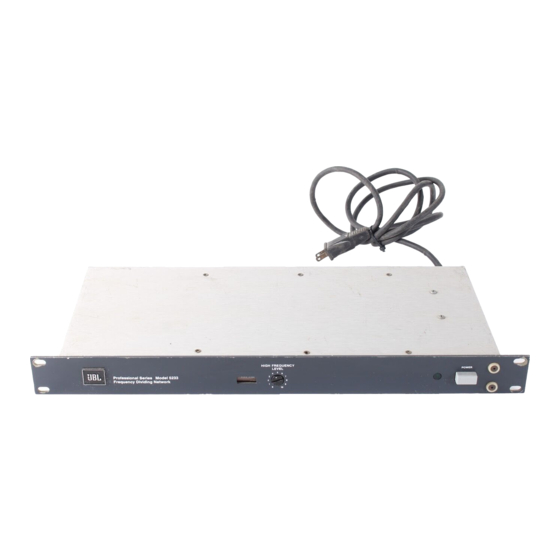
- Page 5 LOUDSPEAKER SYSTEM PROGRAM SOURCE The 5233 or 5234 can be mounted in a single EIA U L T R A - H I G H standard rack space without additional bracing or ventilation. All external connections are made on the rear panel. Mounting HIGH hardware is supplied with each unit.
- Page 6 5234 E L E C T R O N I C F R E Q U E N C Y D I V I D I N G N E T W O R K L O U D S P E A K E R S Y S T E M A M P L I F I E R 5 2 3 4 HIGH...
- Page 7 Bi-Amplified Systems—The following applies to a 5233 or to each channel of a 5234 used in dual channel bi-amplification. 1. With the High Frequency Level control a t " 0 " adjust p r o g r a m...
- Page 9 To install a new crossover card 3. Change the line cord and attachment plug to match the 1. Place the 5233 or 5234 upside d o w n on a soft surface, power source receptacle or use a 120-to-240 V adapter remove the two Phillips-head screws f r o m either side of the (not provided).
- Page 10 R is 4 . 7 k O . Figure 6. 12 dB/Octave Blank Crossover Card (JBL Model 52-5120)
- Page 11 Specific capacitor values are given in Table 6. T a b l e 6. Figure 7. 18 dB/Octave Blank Crossover Card [JBL Model M a x i m u m V a l u e s 51-5130] f o r L o w F r e q u e n c y A t t e n u a t i o n C a p a c i t o r s...
- Page 12 Professional Division James B. Lansing S o u n d , Inc., 8500 Balboa Boulevard, Northridge, California 91329 U.S.A. 5 0 6 8 2 5 2 3 3 - 3 - 1 / 8 - 8 0 R E V B Printed in U.S.A.
Need help?
Do you have a question about the 5233 and is the answer not in the manual?
Questions and answers