Table of Contents
Advertisement
Quick Links
Advertisement
Table of Contents

Summary of Contents for KJB DNG-2300
- Page 1 DNG-2300 Digital white noise generator User Manual ...
- Page 2 Introduction It is well‐known that sound permeates through walls, doors, water, windows and other constructions as well as through voids, cavities and ventilation shafts. This property of materials makes it possible to intercept conversations conducted within premises with the help of highly sensitive ...
-
Page 3: Specification
wood) The SPEAKERS channel can feed up to 12 speakers The MUTE control input allows the user to turn off the speakers temporarily Specification Power source 110‐220 V, 50‐60 Hz Dimensions 6 x 17,5 x 25,4 Weight 2.2 kg Output channels 2 x TRANSDUCERS 1 x SPEAKERS Peak output voltage 12 V TRANSDUCERS output Max. output power 2 x 10 W Frequency response 180‐5600 Hz Minimal impedance of load 3 Ohm Max. quantity of transducers per channel 24 (light structures) 12 (solid structures) SPEAKERS output Max. output power 1 x 8 W Frequency response 180‐7000 Hz Minimal impedance of load 8 Ohm Max. quantity of speakers 12 ... -
Page 4: Front Panel
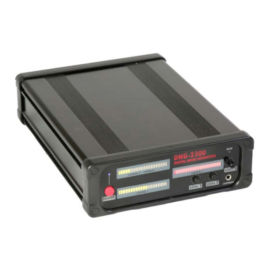
Controls Front panel Figure 1 1. Power switch 2. Level indicator ‐ Channel 1 (TRANSDUCERS 1) 3. Level indicator ‐ Channel 2 (TRANSDUCERS 2) 4. Level indicator ‐ Channel 3 (SPEAKERS) 5. Level 1 adjustment ‐ Channel 1 (TRANSDUCERS 1) 6. Level 2 adjustment ‐ Channel 2 (TRANSDUCERS 2) 7. Mute state of Channel 3 (SPEAKERS) 8. Level 3 adjustment ‐ Channel 3 (SPEAKERS) Rear panel Figure 2 1. TRANSDUCERS output terminals – Channels 1 and 2 2. Muting for Channel 3 (SPEAKERS): contacts open – channel on, contacts closed – channel off 3. SPEAKERS output terminals – Channel 3 4. AC power input ... -
Page 5: Installation
Installation The complete protection system consists of the generator and a number of transducers and speakers uniformly installed in a room on the structures and within the air cavities. While transducers inject the generated noise into surfaces and structures, stopping the distribution of sound ... - Page 6 4Ohm transducers are united as a combination of serial circuits (chains) connected in parallel. The output power is divided between the transducers and is in quadratic dependence on their quantity in a serial chain. The percentage % shows the relative power produced by a transducer, comparing to the "basic" variant with 2 serially connected 4 Ohm transducers. Quantity of Relative power produced by Type of surface transducers in a 4 Ohm transducer serial chain ...
- Page 7 The transducers marked as 100%, 44% and 25% can be mounted on solid surfaces. The transducers marked as 11%, 16% and 25% ‐ on the light surfaces. TD2300 16 Ohm transducers Quantity of Relative power produced by Type of surface ...
- Page 8 transducers in a 16 Ohm transducer serial chain 1 100% Solid 2 25% Solid/Light 3 11% Light ...
- Page 9 Assignment of TRANSDUCERS outputs The DNG‐2300 has two TRANSDUCERS outputs, each capable of feeding up to 12‐24 transducers depending on the density of structures. Grouping the transducers by the density of structure (solid or light) and connecting them to a separate output channel will allow you to adjust the level for each group separately. For example, output “TRANSDUCERS 1” can be ...
- Page 10 Mounting the transducers The TD2300 transducers are supplied with a number of accessories allowing different methods of installation. The method of mounting is selected depending on the type of surface. Direct screw (wood) Plastic dowel (cement, concrete, bricks) Wall anchor (bricks, drywall, fragile materials) Mounting disk (window glass) The accessories for mounting on pipes should be purchased separately: interlocked hose clamp 100‐ 150 mm, bolt M4x8, washer and nut. It is recommended to read the manual supplied with the transducer before starting installation. Quantity and arrangement of speakers Behind dropped ceiling ‐ 1 x SP2300 speaker for each 9‐10 square meters In ventilation shafts, air ducts and other voids – 1 x SP2300 for each void Since the SP2300 is assembled from 3 parts, each being a separate speaker, it is possible to use the 3 individual parts for smaller voids. Disassemble the SP2300 by removing the triangular holder, cut the cables, place the separate speaker parts where necessary and reconnect them in series. Connect the SP2300 speakers in parallel when there is 1, 2 or 3 pieces. For a larger quantity combine speakers in serial pairs. You can connect up to 6 pairs (12 pcs total) ...
-
Page 11: Mounting The Speakers
Attention: Consider the minimum load of 8 Ohm for the ‘SPEAKERS’ outputs when using the modified wiring. Damage to your DNG‐2300 may occur if improperly wired. Mounting the speakers In most cases the speakers do not require mounting and should be placed inside voids or shafts. If the void is not large enough to accommodate the speaker as is, the speaker can be disassembled and placed inside without the triangular holder. If there is no horizontal space sufficient for the speaker, it can be hung on a steel cable. Adjustment of level After the transducers and speakers have been installed and connected to the generator, it is necessary to adjust the level of noise. The front panel of the DNG‐2300 contains the corresponding ... - Page 12 by setting the optimal level of noise which is sufficient for jamming all perimeter‐bound bugging devices. (Please note this is only possible by using auxiliary equipment) With the help of auxiliary equipment (an acoustic leakage probe) it is possible to verify if the DNG‐ 2300 is producing a sufficient level of noise and minimize the audible level in certain cases. An acoustic leakage probe is similar to a wall stethoscope and is designed for the evaluation of how sound is distributed through structures. ...