Table of Contents
Advertisement
Quick Links
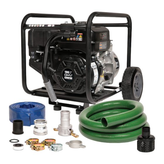
OPERATOR'S MANUAL
MODEL #BD100622
2 iN. (5 cM) SEMi-TRASh WATER PUMP
or visit black-diamond.com
SAVE ThESE iNSTRUcTiONS. This manual contains important safety precautions which should be read and understood before operating the product. Failure to do
so could result in serious injury. This manual should remain with the product.
Specifications, descriptions and illustrations in this manual are as accurate as known at the time of publication, but are subject to change without notice.
EN
3441-M-OP
REV 20220324
Mid-States Distributing, LLC., 2800 Meacham Blvd., Fort Worth, TX 76137 USA
Advertisement
Table of Contents

Subscribe to Our Youtube Channel
Summary of Contents for Black Diamond Equipment BD100622
- Page 1 OPERATOR’S MANUAL MODEL #BD100622 2 iN. (5 cM) SEMi-TRASh WATER PUMP or visit black-diamond.com SAVE ThESE iNSTRUcTiONS. This manual contains important safety precautions which should be read and understood before operating the product. Failure to do so could result in serious injury. This manual should remain with the product.
-
Page 2: Table Of Contents
TABLE Of cONTENTS Table of contents Storage ....................Water Pump Storage ..........introduction . -
Page 3: Introduction
(e.g., messages relating to property damage). your product. Transcribe the information found on your product’s nameplate label to the table below BLACK DIAMOND TECHNICAL SUPPORT TEAM 1-888-373-8272 MODEL NUMBER BD100622 SERIAL NUMBER DATE OF PURCHASE PURCHASE LOCATION... -
Page 4: Important Safety Instructions
iMPORTANT SAfETY iNSTRUcTiONS WARNiNG WARNiNG Cancer and Reproductive Harm – www.P65Warnings.ca.gov Spark from removed spark plug wire can result in fire or electrical shock. DANGER When servicing the water pump: Disconnect the spark plug wire and place it where it cannot Water pump engine exhaust contains carbon monoxide, contact the plug or any other metal object. - Page 5 iMPORTANT SAfETY iNSTRUcTiONS DANGER cAUTiON The water pump develops powerful force. Improper treatment or use of the water pump can damage it, shorten its life and void your warranty. DO NOT move the water pump when it is in use. Use the water pump only for intended uses.
-
Page 6: Fuel Safety
iMPORTANT SAfETY iNSTRUcTiONS fuel Safety When transporting or servicing the water pump: Make certain that the fuel valve is in the OFF position, the gasoline DANGER tank is empty. Disconnect the spark plug wire. GASOLINE AND GASOLINE VAPORS ARE HIGHLY FLAMMABLE AND EXPLOSIVE. -
Page 7: Safety And Dataplate Labels
Champion Power Equipment. 1966-L-SF Colors MID-STATES MODEL / MODÈLE DISTRIBUTING, LLC. Size 59 x 47 mm BD100622 2800 MEACHAM BLVD Artwork Notes Revision Changes Dataplate FLOW (GPM / LPM) FORT WORTH, TX 76137 159 / 600 DÉBIT (GPM / LPM) -
Page 8: Safety Symbols
iMPORTANT SAfETY iNSTRUcTiONS Safety Symbols Some of the following symbols may be used on this product. Please study them and learn their meaning. Proper interpretation of these symbols will allow you to more safely operate the product. SYMBOL MEANING Read Operator’s Manual. To reduce the risk of injury, user must read and understand operator’s manual before using this product. - Page 9 iMPORTANT SAfETY iNSTRUcTiONS SYMBOL MEANING Toxic Fumes. The engine exhaust from this product contains chemicals known to the state of California to cause cancer and birth defects and other reproductive harm. Risk of Asphyxiation. This engine emits carbon monoxide, an odorless, colorless poison gas. Breathing carbon monoxide can cause nausea, fainting or death.
-
Page 10: Operation Symbols
iMPORTANT SAfETY iNSTRUcTiONS Operation Symbols Some of the following symbols may be used on this product. Please study them and learn their meaning. Proper interpretation of these symbols will allow you to more safely operate the product. SYMBOL MEANING SYMBOL MEANING Choke. -
Page 11: Controls And Features
cONTROLS AND fEATURES Read this operator’s manual before operating your water pump. Familiarize yourself with the location and function of the controls and features. Save this manual for future reference. 1. Fuel Tank Cap 11. Throttle 2. Fuel Tank 12. Transport Handle 3. -
Page 12: Parts Included
cONTROLS AND fEATURES Parts included Assembly Parts Part Part Qty. Hardware Needed Hardware Qty. Tool Needed Pin Ø2 x 33, “R” Shape Wheels Roll Pin Ø16 x Ø10 x 97 Flange Bolt M8x16 1× 12mm wrench or socket Support Leg w/Vibration Mounts Nut M8 1×... -
Page 13: Assembly
ASSEMBLY Your water pump requires some assembly. This unit ships from the factory without oil. It must be properly serviced with fuel and oil before operation. For questions regarding the assembly of your water pump, call our help line at 1-888-373-8272. Please have your serial number and model number available. -
Page 14: Add Fuel
ASSEMBLY NOTicE NOTicE The recommended oil type is 10W-30 automotive oil. The first 5 hours of run time is the break-in period for the engine. During the break in period, it is recommended to use If running engine in extreme temperatures, refer to the standard automotive, non-synthetic blended oils. - Page 15 ASSEMBLY NOTicE Our engines work well with 10% or less ethanol blended gasoline. When using ethanol-gasoline blends there are some issues worth noting: – Ethanol-gasoline blends can absorb more water than gasoline alone. – These blends can eventually separate, leaving water or a watery goo in the tank, fuel valve and carburetor.
-
Page 16: Operation
OPERATiON Water Pump Location Place the water pump on a flat, level surface. The pump should be placed close to the water level to ensure maximum pump performance. DANGER Pump output will be affected by the type, length, and size of the Water pump engine exhaust contains carbon monoxide, suction and discharge hoses. - Page 17 OPERATiON 2. Thread the assembled connector to the outlet fitting (top of NOTicE pump). Locate the blue “outlet” label on the pump. You may use a small amount of dish soap on the outlet hose fitting to help ease the outlet hose on the fitting. Work the soap around the fitting with your finger.
- Page 18 OPERATiON 2. Cut ties and uncoil the green hose and use some weight to 6. Slide the clamps back and start to assemble the green hose help straighten the hose out. Best to do this on a warmer day to cam lock coupler. in the sun.
- Page 19 OPERATiON 9. Rotate and align the clamp bolts so you have clearance for 13. Wrap the green inlet clockwise with the Teflon tape provided ® the cam levers to lock in place later. with 4 complete wraps. 10. Tighten each clamp to 11.1±1.5 lbf-ft (15±2 Nm) with a 10mm 14.
-
Page 20: Priming The Pump
OPERATiON 20. Slide the clamp just before the end of the green hose. NOTicE If the cam levers do not clamp down completely, rotate and align the clamp bolts so you have clearance for the cam levers to lock. See step 9 earlier. 17. -
Page 21: Before Starting The Engine
OPERATiON 1. Remove the priming cap (top) and fill pump body to the very top of outlet flange with water. Reinstall the priming plug. DO NOT over tighten. 3. Move the choke lever to the “CHOKE” position. 2. As the engine starts up, this will start the draw of liquid into the pump. -
Page 22: Stopping The Engine
OPERATiON 5. Press engine switch to “ON” position. WARNiNG DO NOT remove either top cap or bottom plug while the water pump is on and running. Loss of pressure and suction will occur. Injury may also occur. Stopping the Engine In an emergency, turn the engine switch to the “OFF”. -
Page 23: Operation At High Altitude
OPERATiON Operation at high Altitude The density of air at high altitude is lower than at sea level. Engine power is reduced as the air mass and air-fuel ratio decrease. Engine power and water pump output will be reduced approximately 3½% for every 1000 ft. of elevation above sea level. -
Page 24: Maintenance
MAiNTENANcE Make certain that the water pump is kept clean and stored properly. Only operate the unit on a flat, level surface in a clean, dry operating environment. DO NOT expose the unit to extreme conditions, excessive dust, dirt, moisture or corrosive vapors. WARNiNG ... -
Page 25: Cleaning The Air Filter
MAiNTENANcE 2. Use a spark plug socket tool (included), or a 13/16 in. 6. Place the filter in the assembly. (21 mm) (not included) socket to remove the plug. 7. Reattach the air filter cover. Attach the side closest to the 3. -
Page 26: Adjusting The Governor
MAiNTENANcE Adjusting the Governor EVERY 100 HOURS OR EVERY SEASON — Change oil WARNiNG — Clean/adjust spark plug Tampering with the factory set governor will void your — Check/adjust valve clearance* warranty. — Clean spark arrester — Clean fuel tank and filter* The air-fuel mixture is not adjustable. -
Page 27: Storage
STORAGE Refer to the Maintenance section for proper cleaning instructions. 6. Clean the engine according to the Maintenance section. 7. Change the oil. Water Pump Storage 8. Remove the spark plug and pour about 1⁄2 oz. (14.9 mL) of oil 1. - Page 28 STORAGE Protect your water pump from freezing. 1. Apply all storage instructions from previous sections. 2. Make sure water pump is free of all water before storing for winter. 3. In order to prevent the pump from freezing you will need to insert RV antifreeze.
-
Page 29: Specifications
SPEcificATiONS Water Pump Specifications Engine Oil Specifications Water Pump Type ........Semi-trash DO NOT OVERFILL. Port Diameter (in./cm) ........2.0/5 Type .......... -
Page 30: Troubleshooting
TROUBLEShOOTiNG Problem Cause Solution Allow engine to cool for 2 minutes, then fill fuel No fuel. tank. Fill or check oil is to the proper level; place water Low oil. pump on a flat, level surface. Replace spark plug or check spark plug cable is Pump will not start. - Page 31 TROUBLEShOOTiNG Problem Cause Solution Choke is in the wrong position. Slide choke lever to the RUN position. Spark plug wire is loose. Attach wire to spark plug securely. Pump starts, but runs roughly. Faulty spark plug. Replace spark plug. Allow engine to cool for 2 minutes, then drain Fuel is contaminated (water, debris, etc.).
-
Page 32: Warranty
WARRANTY Other Exclusions CHAMPION POWER EQUIPMENT 2 YEAR LIMITED WARRANTY This warranty excludes: – Cosmetic defects such as paint, decals, etc. Warranty Qualifications – Wear items such as filter elements, o-rings, etc. To register your product for warranty and FREE lifetime call center –... - Page 33 CHAMPION POWER EQUIPMENT, INC. (CPE) AND THE UNITED STATES ENVIRONMENT PROTECTION AGENCY (U.S. EPA) EMISSION CONTROL SYSTEM WARRANTY Your Champion Power Equipment (CPE) engine complies with U.S. EPA emission regulations. YOUR WARRANTY RIGHTS AND OBLIGATIONS: T T h h e U e US E S EP P A A A and CP P E a...
- Page 34 EMISSION CONTROL SYSTEM WARRANTY The following are specific provisions relative to your Emission Control System (ECS) Warranty Coverage. 1. APPLICABILITY: This warranty shall apply to 1997 and later model year small off-road engines (SORE). The ECS Warranty Period shall begin on the date the new engine or equipment is delivered to its original, end-use purchaser, and shall continue for 24 consecutive months thereafter.
- Page 35 EMISSION-RELATED PARTS INCLUDE THE FOLLOWING: (using those portions of the list applicable to the engine) Systems covered by this Parts Description warranty Fuel Metering System Fuel regulator, Carburetor and internal parts Air Induction System Air cleaner, Intake manifold Ignition System Spark plug and parts, Magneto ignition system Exhaust System Exhaust manifold, catalytic converter...
Need help?
Do you have a question about the BD100622 and is the answer not in the manual?
Questions and answers