Table of Contents
Advertisement
Quick Links
Advertisement
Table of Contents

Summary of Contents for Boulton Pumps ESK Series
- Page 1 Chemical Process Centrifugal Pumps Instructions for operation and maintenance...
- Page 2 Instructions for Installation, Operation and Maintenance. Boulton pumps All rights reserved. Can not be copied or reproduced for any purpose without permission. 07.2020 Revision 1...
-
Page 3: Table Of Contents
Content 1. GENERAL........................................................3 1.1. IDENTIFICATION OF SAFETY AND WARNING SYMBOLS....................................... 3 1.2. GENERAL INSTRUCTIONS ................................................. 3 1.3. SAFETY INSTRUCTIONS ..................................................4 1.3.1. CE signs and approvals ................................................4 1.3.2. Explosive atmosphere ................................................5 1.3.3. Monitoring ....................................................8 1.3.4. Constructional requirements ..............................................8 1.3.5. -
Page 4: General
The user is responsible for the verification of the ambient conditions where the pump will be stored or installed. - BOULTON PUMPS does not guarantee repairs or alterations done by user or other unauthorized personnel. The use of original spare parts and accessories authorized by manufacturer will ensure safety. -
Page 5: Safety Instructions
1.3. SAFETY INSTRUCTIONS Strictly obey to the following instructions to prevent personal injuries and/or equipment damages: - Pump should be used only in the specified operating conditions. - Any weight, stress or strains on the piping system should not be transmitted to the pump. - Electrical connections on the motor or accessories must always be carried out by authorized personnel and in accordance to the local codes. -
Page 6: Explosive Atmosphere
1.3.2. Explosive atmosphere This section should be read carefully for the pumps operating at explosive atmospheres. Only the products certificated for the explosive atmospheres should be used at the explosive atmospheres. Detailed information about the operating conditions at the explosive atmospheres are found in Directive on Equipment for Potentially Explosive Atmospheres 2014/34/UE (ATEX). - Page 7 Temperature class of the Maximum surface Maximum fluid temperature centrifugal pump temperature 200ºC 180ºC 135ºC 110ºC Table 1 The user must check that the minimum ignition temperature of the flammable substances present or pumped is: For pumps marked T4: Higher than 135°C for flammable gases and vapours or temperature class T4, T3, T2 or For pump with T3 marking: Over 200°C for flammable gases and vapours or temperature class T3, T2 or T1.
- Page 8 The pump and its associated parts (motor, baseplate, pipes, etc.) must be equipotential and properly grounded. 1.3.2.3. Equipment with ATEX marking The centrifugal pumps of the ESN-EX and ESH-EX series can be supplied with ATEX marked equipment from other manufacturers (motor, flexible coupling, mechanical seal). The installed electrical and/or mechanical equipment, with a given ATEX marking by third party manufacturers, must be checked and maintained according to the instructions given by the manufacturers of such equipment and with the frequency indicated in their corresponding manuals.
-
Page 9: Monitoring
1.4. RECYCLING For products and arts, which will not be used and scraped, use the local or private waste collection services. If it is not possible, consult the nearest authorized service centre of Boulton Pumps. -
Page 10: Esk Pumps
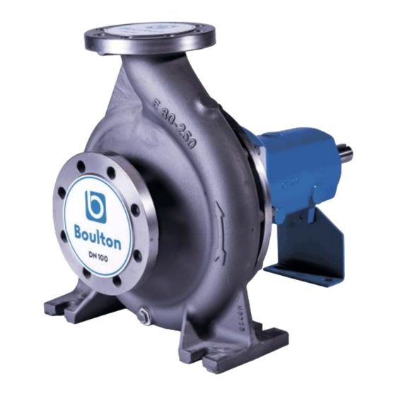
ESK PUMPS 2.1. GENERAL 2.1.1. Pump Description ESK series pumps are horizontal, radially split volute casing, single stage, end suction centrifugal pumps with closed or semi-open impeller. Dimensionally complies with EN 22858 / ISO 2858. 2.1.2. Applications ESK series pumps are suitable for clean or slightly contaminated (max. 20 mg/dm³) liquids with low viscosities and temperatures up to 175 ºC. -
Page 11: Technical Data
Carefully remove the packaging material and check that pump and accessories (if any) are free from any markings, stretches and damages, which may have occurred during transportation. In the event of damage, report this immediately to BOULTON PUMPS service department and to the transport company. 2.2.2. Transport 2.2.2.1. -
Page 12: Storage
Fig. 1a. Bare shaft pump Fig. 1b. Pump and motor over a baseplate 2.2.3. Storage If the pump is not to be installed and operated soon after arrival, store the pump in a clean, dry and frost-free place with moderate changes in ambient temperature. ... -
Page 13: Preparation For Installation
Motor mounting position (foot mounted, flange mounted, horizontal, vertical, etc.). When selecting the coupling, nominal motor power and operating speed must be taken into account. 2.3.2. Preparation for Installation Before installing the pump: Clean the suction and discharge flanges thoroughly. ... -
Page 14: Coupling Alignment
Fig. 3. Aligning a flexible coupling “Coupling Alignment” means to secure the motor and pump rotation axes on the same straight line. ESK series pumps are dispatched from our factory after the coupling alignment is precisely secured if supplied with driver and baseplate. A certain amount of deformation of the baseplate is possible during handling and transit. -
Page 15: Connecting The Piping
2.3.5. Connecting the Piping 2.3.5.1. General Never use the pump as an anchorage point or as a carrier for the piping. The pipes should be supported very near the pump (Fig. 5). It must be checked that any weight, stress or strains on the piping system should not be transmitted to the pump. - Page 16 2.3.5.3. Discharge piping (Fig. 6) A control valve should be installed in the discharge pipe, as close to the pump as possible, to regulate the required flow and head. If the total head of the pump exceeds 10 meters or if discharge line is of appreciable length a non return valve should be installed between the pump and isolating valve on the discharge line to protect the pump against water hammer and reverse flow on shut down.
- Page 17 d1 : Pressure gauge (discharge). d2 : Pressure gauge (suction). d3 : Filling or vent. d4 : Drain. d5 : Oil filling. d6 : Oil drain. d7 : Oil sight gauge. d8 : Seal leakage drain. Fig.8 S1 : Seal flushing liquid inlet from external source. Fig.9 e1: Double mechanical seal buffer liquid inlet from external source.
- Page 18 2.3.5.6. Electrical Connections The electrical motors have to be built in accordance with EN 60034-1. Enclosures of electrical motors and control systems on the pump unit shall as a minimum give protection in accordance with EN 60529 IP22. But in determining the degree of protection of enclosures of electrical motors and control systems on the pump unit the operating and environmental conditions must be taken into consideration.
-
Page 19: Start Up / Shut Down
In the case of three-phase induction motors with Y / ∆ – connection it must be ensured that the change- over points between star and delta follow on from one another very quickly. Longer change-over times may result in pump damage (Table 2). Motor Power Y –set time ≤... -
Page 20: Start Up The Pump
2.4.1.4. Checking the direction of rotation ESK type pumps rotate in clockwise when it is looked from coupling to the pump. This direction is already indicated on the pump nameplate by an arrow. Check this by switching the pump on, then off again immediately. Fit the coupling guard back in place if you took it out. -
Page 21: Lubrication
If the pump has soft packing type stuffing boxes, these should drip during operation. The gland nuts should only be lightly tightened. In case of excessive leakage from the stuffing box tighten the gland nuts slowly and evenly until the leakage is reduced to the dripping state. -
Page 22: Disassembly, Repair And Reassembly
2.6. DISASSEMBLY, REPAIR AND REASSEMBLY Before starting work on the pumpset, make sure it is disconnected from the mains and can not be switched on accidentally. Follow the safety precaution measures outlined in “safety instructions”. 2.6.1. Disassembly Close all valves in the suctions and discharge lines, and drain the pump by opening the drain plug (230). ... -
Page 23: Shaft Seal
2.6.3. Shaft seal 2.6.3.1. Pump with soft packing gland While starting to change soft packing thoroughly clean the stuffing box and shaft sleeve. Cut enough number of pieces at the suitable length diagonally from suitable size of soft packing. Roll it up over the shaft sleeve and see the ends are in full contact. -
Page 24: Spare Parts
2.7. SPARE PARTS BOULTON PUMPS guarantees to supply the spare parts for ESK type pumps for 10 years. You can provide any spare parts easily. Inform us about the following details on the name-plate, when you order spare parts. Pump Type and Size... - Page 25 POSSIBLE CAUSES REMEDIES Fill pump and piping completely with liquid and repeat the priming There may be air existing in pump or piping. procedure. Check for leaks in suction pipe joints and fittings. Check shaft seal if Ingress of air through shaft seal, suction pipe necessary increase the pressure of sealing liquid.
-
Page 26: Tightening Torques
2.9. TIGHTENING TORQUES TIGHTENING TORQUES Tightening Torque max (Nm) Thread Diameter (Ø) Property Classes 10.9 1050 1100 1550 1450 2100 1970 2770 2530 3560 Table 8 2.10. EXPECTED NOISE VALUES Sound pressure level (dB) * Power of motor Pump with motor (Kw) ��... -
Page 27: Permissible Forces And Moment At The Pump Flanges And Weights
2.11. PERMISSIBLE FORCES AND MOMENT AT THE PUMP FLANGES AND WEIGHTS TYPE ∑ �� ∑ �� �� �� �� ℎ �� 32-160 1300 1600 32-200 40-200 1400 1000 1700 40-250 50-160 50-200 1500 1100 1800 50-250 50-315 65-160 65-200 1800 1300 2200 65-250... -
Page 28: Pump Dimension Groups And Weights
2.12. PUMP DIMENSION GROUPS AND WEIGHTS Dimension Characteristics Dimensions Pump Type Weight (kg) Group Shaft Diameter / f (length) 32-160 50-160 32-200 Ø24 / 385 40-200 50-200 65-160 65-200 80-200 100-200 125-200 Ø32 / 500 40-250 50-250 65-250 80-250 50-315 150-200 Ø42 / 545 100-250... -
Page 29: Sectional Drawings
2.13. SECTIONAL DRAWINGS M1 – STANDARD MOUNTING PART LIST Volute casing Key (Coupling) Casing cover Circlip Support foot Grain plug Wear ring (Casing) Oil filling Wear ring (Casing cover) Oil drain Wear ring (Front) Oil level gauge Bearing bracket Stud Bearing bracket lantern Hex. - Page 30 M2 – SEMI-OPEN IMPELLER APPLICATION PART LIST Wear plate (front) Wear plate (back) Casing cover (semi-open impeller) Impeller (semi-open) Allen bolt Allen bolt...
- Page 31 M3 – FLUSHING FROM EXTERNAL SOURCE PART LIST Volute casing Circlip Casing cover Grain plug Support foot Oil filling Wear ring (Casing) Oil drain Wear ring (Casing cover) Oil level gauge Bearing bracket Stud Bearing bracket lantern Hex. head bolt Bearing cover (Outboard) Hex.
- Page 32 www.boultonpumps.com Instructions for operation and maintenance Pol. Industrial de Santelices, 7 48550 Muskiz (Bizkaia) - Spain +34 946 510 116 info@boultonpumps.com 07/2020...