Table of Contents
Advertisement
Quick Links
Advertisement
Table of Contents

Summary of Contents for Malta Dynamics A6101
- Page 1 Beam Trolley Instruction Manual A6101...
- Page 2 Beam Trolley INSTRUCTION MANUAL These instructions apply to the following model(s): A6101 Manual Revision: MARCH 30, 2021 A copy of this manual must be available to users at all times. Visit www.MaltaDynamics.com for the latest user instruction manual based upon date of manufacture.
-
Page 3: Table Of Contents
TABLE OF CONTENTS Under Penalty of Law ------------------------------------------------- Materials and Construction ------------------------------------------- Purpose ----------------------------------------------------------------- Instructions for Use ---------------------------------------------------- Limitations for Use ----------------------------------------------------- Connector Compatibility Limitations --------------------------------- Instructions ------------------------------------------------------------ Product Labels -------------------------------------------------------------- 13 Training --------------------------------------------------------------------- 14 Inspection ----------------------------------------------------------------- Maintenance and Cleaning ------------------------------------------- Inspection Log ---------------------------------------------------------... -
Page 4: Under Penalty Of Law
Aluminum alloy. PURPOSE The A6101 is an anchorage connector designed to function as an interface between the anchorage and a fall protection, work positioning, rope access, or rescue system for the purpose of coupling the system to the anchorage. Any references to “anchorage connector”... -
Page 5: Instructions For Use
Read This Instruction Manual Carefully Before Using This Equipment. Do not alter or intentionally misuse this equipment. INSTRUCTIONS FOR USE A user must be of sound mind and body to properly and safely use this equipment in normal and emergency situations. Users must have a physician ensure they are clear of any medical conditions that may affect the proper and safe use of this equipment in normal and emergency situations. -
Page 6: Limitations For Use
LIMITATIONS FOR USE Do not use this equipment if you are unable to tolerate the impact of a fall arrest. Age and fitness can seriously affect your ability to withstand a fall. Consult with a physician if in doubt. Minors, pregnant women, and anyone with a history of back and/or neck problems must not use this equipment. -
Page 7: Connector Compatibility Limitations
Use of a non-locking snap hook can result in rollout (a process by which a snap hook or carabiner unintentionally disengages from another connector or the object to which it is coupled (ANSI Z359.0- 2012). Malta Dynamics connectors (snap hooks and carabiners) are designed to be used only as specified in each product’s user’s instructions. - Page 8 (unless the manufacturer’s instructions for both the lanyard and connector specifically allow such a connection). • A snap hook connected to a D-Ring, Rebar, or other connection point with improper dimensions/configurations could cause the snap hook keeper to become depressed by the turning motion of the snap hook; the snap hook or carabiner may not fully close and lock or roll-out may occur.
-
Page 9: Instructions
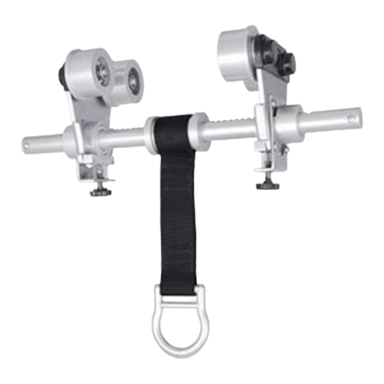
(Rollers) (Rollers) (Notches) (Notches) (Toggle Plate) (Toggle Plate) (Secondary Safety Lock) (Secondary Safety Lock) (5,000-lbf Swivel) INSTRUCTIONS: 1. Locate a structural steel beam flange capable of withstanding a 5,000- lbf (22kN). static load or meeting OSHA 1926.502 requirements for a safety factor of two. - Page 10 4. Slide the adjustable rollers so that both sets of rollers are fully resting on the beam flange. 5. Release the toggle plate and pull back on the adjustable rollers to ensure the ratchet teeth are fully seated in the nearest ratchet notches.
- Page 11 LOADING CONDITIONS DIAGRAM LOADING CONDITIONS DIAGRAM ACCEPTABLE LOADING 30° MAX 30° MAX Placement at or below a user’s working height requires integration of a compatible ANSI Z359.1 shock-absorbing lanyard that does not allow the user to extend more than 6 feet (in any direction) from the anchorage connector before the shock absorber is activated.
- Page 12 *The user shall be equipped with a means of limiting the maximum dynamic forces exerted on the user during the arrest of a fall to a maximum of 8 kN (1800-lbf ). In the EU these forces must be limited to 6 kN (1350- lbf ).
-
Page 13: Product Labels
PRODUCT LABELS The following labels are affixed to the product and must not be removed: WARNING LABEL BEAM TROLLEY A6101 Model: 5,000-lbf (22kN) UTS (1) person 310-lbs (140kg) Aluminum, Zinc Plated Steel, Stainless Steel Batch # BTA-XXX WARNING: It is essential to the safety of the end user that the seller of this device include all instructions pertaining to the proper use, maintenance and inspection of the device in the language of the country in which the product is to be sold. -
Page 14: Training
TRAINING Employers must provide training to any employee who may be exposed to fall hazards in order to enable the employee to recognize and reduce fall hazards. Training must be conducted by a Competent or Qualified Person. Trainer and trainees must not be exposed to fall hazards during the training course. This equipment is intended to be used by persons trained in its correct application and use. -
Page 15: Maintenance And Cleaning
MAINTENANCE & CLEANING Wipe off all surface dirt. Clean with compressed air and/or a stiff brush using plain water or a mild soap and water solution to clean away contaminants; wipe hardware dry with a clean cloth. Hang away from heat and allow to dry completely. -
Page 16: Inspection Log
INSPECTION LOG Date of Manufacture: __________________________________________________ Model Name/Number: _________________________________________________ Serial: ________________________________________________________________ Date of First Use: _____________________________________________________ Inspection Date Items Noted Corrective Action Approved By Easy Slider I-Beam Anchor User Instruction Manual Revision Code: Manual MaltaDynamics.com | 800-494-1840 MARCH 30,2021... -
Page 17: Warranty
LIMITED REMEDY: Upon notice in writing, Malta Dynamics will repair or replace all defective items at Malta Dynamics’s sole discretion. Malta Dynamics reserves the right to require that the defective item be returned to its plant for inspection before determining the appropriate course of action.
Need help?
Do you have a question about the A6101 and is the answer not in the manual?
Questions and answers